
Instruction Manual

MAX11300PMB1 Peripheral Module and Munich (USB2PMB1) Adapter Board Quick Start Guide
6. Examples
The MAX11300PMB1 software includes a number of waveform plots and examples
for configuring and testing the MAX11300.
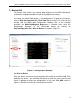
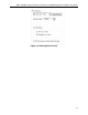
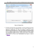
Figure 15 lists the files provided with the software tool. The files with suffix .ADC are
predefined waveform plots that can be used as input values to ports configured in
DAC mode. The files with suffix .csv are example configurations showing different
ways the MAX11300 can be configured. The files with suffix .mpix are design files
from MAX11300 configuration software.
Figure 15. MAX11300PMB1 Files
The Munich GUI is provided with an example configuration file for the examples in
Figure 15. To create a configuration file, a separate tool is needed: MAX11300
Configuration Software.
A step-by-step guide to use example register file is as follows:
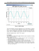
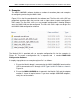
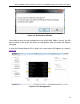
1. Ensure the Munich board is connected to the MAX11300PMB1 board and the
USB is connected to a PC through a USB Type A to Mini B Cable as shown in
Figure 16.
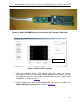
2. Ensure the MAX11300PMB tab is opened in the Munich GUI and the adapter
number is shown in top-left corner. If you have multiple USB2PMB adapters,
verify the serial numbers.
17