
Instruction Manual

MAX11300PMB1 Peripheral Module and Munich (USB2PMB1) Adapter Board Quick Start Guide
The functions supported by the MAX11300 GUI are as follows:
• Configuration
• Get predefined waveform files
• Choose sample delay and single or continue scan mode
• View/save plots
• Plot view options
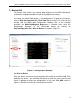
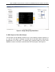
Once the MAX11300 device is configured, click Scan Continuously. The GUI
then exercises each port with the programmed function.
5.2 Part Configuration
If the port is configured as:
a. General-Purpose Input Port (GPI): The user-defined logic level is
read from the port and written to the appropriate port box.
b. General-Purpose Output Port (GPO): The user-defined logic level
defined in the port text box is written to the port (use either 0/1 or
high/low).
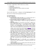
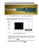
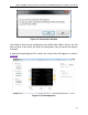
c. DAC Analog Output: The value written to the text box is applied to the
port. For DAC analog outputs, it is also possible to apply a complete
waveform. To do that, select a target DAC-port, and to apply a
waveform, click on Get Plot Box on the top right. A separate window
opens, and a comma separated file (.adc) that contains hex or decimal
numbers can be read with up to 1024 samples (Figure 12
). There are
a few waveform examples provided for sawtooth and sine and triangle
waveforms; these files have the suffix .adc
*
. Note that once a plot box
for the port is open, the text box in the GUI main window is ignored.
d. ADC Analog Input: the hexadecimal number in the text box
corresponds to the voltage applied to the pin. Note that the ADC input
type and the input range is selected in the configuration tool. As with
the DAC configuration, you can also open a plot box by selecting the
appropriate pin and clicking on Get Plot Box on the top right. If a plot
box is open, the plot box shows the waveform applied to the ADC input
pin.
e. Differential ADC Input: The MAX11300 can be configured for
differential ADC mode using two ports. The operation of the GUI is the
same as in step d.
f. Level Translator: The IC acts correctly, but the GUI shows only static
values for the input and the output.
*Although the files have suffix .adc, the content is a simple hex value that can either be a file saved from an
ADC analog input or as file that can be opened and written to a DAC to provide an analog output.
13