
Instruction Manual

MAX11300PMB1 Peripheral Module and Munich (USB2PMB1) Adapter Board Quick Start Guide
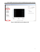
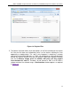
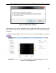
5. Munich GUI
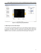
The Munich GUI contains the internal block diagram of the MAX11300 device
showing the 20 programmable I/Os with their programmed setting.
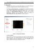
At startup, the MAX11300 device is not programmed. To program the device,
click on Chip Configuration File | Read from File and select a .csv file that was
created with the MAX11300 Configuration Software tool. In the example
provided, the MAX11300Register_Demo.csv is selected. Next, write this
configuration bitstream to the MAX11300 device by clicking on
Chip Configuration File | Write to Device as shown in Figure 11.
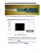
Figure 11. Configuration Example
5.1 Write to Device
Click this button to transfer the configuration bit stream to the MAX11300. After
updating the device, use the Scan command to read the status and the port
name is updated to reflect the configuration. In this case, P10_ADC shown in
Figure 11 denotes that Port 10 is configured as an ADC.
12