
Datasheet


www.maximintegrated.com
Maxim Integrated
│
12
MAX11200/MAX11210 24-Bit, Single-Channel, Ultra-Low-Power,
Delta-Sigma ADCs with GPIO
This selects all GPIO as outputs, as well as setting all
logic signals to 0 except the selected channel AIN1. To
select channel AIN3 next, it is best to set all switches to
a high-impedance state first (see Table 4b).
Then select channel AIN3 by driving IN3 high (see
Table 4c).
It is not always necessary to transition to a high-imped-
ance state between channel selections, but depends on
the source analog signals as well as the control structure
of the multiplexed switches.
Digital Programmable Gain (MAX11210)
The MAX11210 offers programmable gain settings that
can be digitally set to 1, 2, 4, 8, or 16. The DGAIN_ bits in
the CTRL3 register (Table 14) configure the digital gain
setting and control the input referred gain. See Figure 4.
The MAX11210’s input range is 0V to V
REF
/gain (unipo-
lar) or ±V
REF
/gain (bipolar). The MAX11210 modulator
produces 32 bits of data, but only 24 bits of data are
used. For any given data rate, the noise floor remains
constant, independent of the digital gain setting. The
MAX11210 digital gain is beneficial for systems that can
afford averaging multiple readings for higher resolution.
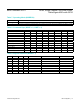
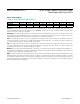
Table 4c. Data Command to Select Channel AIN3 in Figure 3
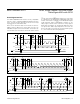
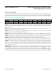
Figure 4. MAX11210 Digital Programmable Gain Example (1sps Output Rate)
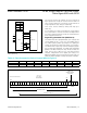
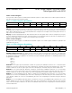
Figure 3. MAX11200 GPIOs Drive an External 4-Channel
Switch (MAX313)
BIT B7 B6 B5 B4 B3 B2 B1 B0
BIT NAME
DIR4 DIR3 DIR2 DIR1 DIO4 DIO3 DIO2 DIO1
VALUE
1 1 1 1 0 1 0 0
MSB
LSB
NOISE FLOOR
REMAINS CONSTANT
AT 0.21µV
RMS
BITS USED FOR GAIN = 16
BITS USED FOR GAIN = 2
BITS USED FOR GAIN = 1
SUB-LSBs
24-BIT OUTPUT DATA CYCLE
V
REF
= 3.6V,
V
LSB
= 429nV,
BIPOLAR RANGE
AIN1
AIN2
AIN3
AIN4
IN1
IN2
IN3
IN4
COM1
COM2
COM3
COM4
GPIO1
GPIO2
GPIO3
GPIO4
AINP
AINN
MAX313
LOGIC SWITCH
0 OFF
1ON
MAX11200MAX313