
Datasheet


13Maxim Integrated
20-Bit, Single-Channel, Ultra-Low-Power, Delta-
Sigma ADCs with Programmable Gain and GPIO
MAX11206/MAX11207
It is not always necessary to transition to a high-imped-
ance state between channel selections, but depends on
the source analog signals as well as the control structure
of the multiplexed switches.
Digital Programmable Gain (MAX11206)
The MAX11206 offers programmable gain settings that
can be digitally set to 1, 2, 4, 8, 16, 32, 64, or 128. The
DGAIN_ bits in the CTRL3 register (see Table 14) config-
ure the digital gain setting and control the input referred
gain. The MAX11206’s input range is 0V to V
REF
/
gain (unipolar) or ±V
REF
/gain (bipolar). The MAX11206
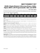
always outputs 20 bits of data. But as this is a digital
programmable gain, the noise floor remains constant,
depending on the output rate setting. At an output rate of
10sps, as shown in Figure 4, the noise floor is such that
all gain settings from 1 to 64 provide 20 bits of noise-free
resolution. A gain setting of 128 at 10sps means the LSB
is below the noise floor. The MAX11206 digital gain is
beneficial for low-voltage applications that only require a
small portion of the 0V to V
REF
or ±V
REF
ranges.
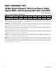
Table 4c. Data Command to Select Channel AIN3 in Figure 3
Figure 4. MAX11206 Digital Programmable Gain Example (10sps Output Rate)
Figure 3. MAX11206 GPIOs Drive an External 4-Channel
Switch (MAX313)
AIN1
AIN2
AIN3
AIN4
IN1
IN2
IN3
IN4
COM1
COM2
COM3
COM4
GPIO1
GPIO2
GPIO3
GPIO4
AINP
AINN
MAX313
LOGIC SWITCH
0 OFF
1ON
MAX11206MAX313
MSB
NOISE FLOOR
REMAINS CONSTANT
AT 0.55µV
RMS
BITS USED FOR GAIN = 16
BITS USED FOR GAIN = 2
BITS USED FOR GAIN = 1
SUB-LSBs
20-BIT OUTPUT DATA CYCLE
V
REF
= 3V
LSB
BITS USED FOR GAIN = 128
BIT B7 B6 B5 B4 B3 B2 B1 B0
BIT NAME
DIR4 DIR3 DIR2 DIR1 DIO4 DIO3 DIO2 DIO1
VALUE
1 1 1 1 0 1 0 0