
Datasheet
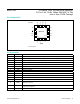
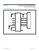


MAX11190 4-Channel, Dual, Simultaneous Sampling,
2.2V to 3.6V, 12-Bit, 3Msps SAR ADC in Tiny
3mm x 3mm TQFN Package
www.maximintegrated.com
Maxim Integrated
│
17
Denitions
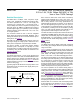
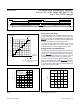
Integral Nonlinearity
Integral nonlinearity(INL)isthedeviationofthevalueson
an actual transfer function from a straight line. For these
devices, the straight line is a line drawn between the end
points of the transfer function after offset and gain errors
are nulled.
Differential Nonlinearity
Differentialnonlinearity (DNL) is the differencebetween
anactualstepwidthandtheidealvalueof1LSB.ADNL
errorspecificationof±1LSBorlessguaranteesnomiss-
ing codes and a monotonic transfer function.
Offset Error
Offset error is the deviation of the first code transition
(00 . . . 000) to (00 . . . 001) from the ideal, that is, AGND
+0.5LSB.
Gain Error
Gain error is the deviation of the last code transition
(111 . . . 110) to (111 . . . 111) from the ideal after adjusting
for the offset error, that is, V
REF
-1.5LSB.
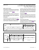
Aperture Jitter
Aperture jitter (t
AJ
) is the sample-to-sample variation in
the time between the samples.
Aperture Delay
Aperture delay (t
AD
) is the time between the falling edge
of the sampling clock and the instant when an actual
sample is taken.
Aperture Delay Matching
Aperture delay (t
ADM
) is the difference between the aper-
ture delay between channel A and B measured at the fall-
ing edge of the sampling clock for the sample taken from
the identical analog input.
Signal-To-Noise Ratio (SNR)
SNR is a dynamic figure of merit that indicates the con-
verter’s noise performance. For a waveform perfectly
reconstructed from digital samples, the theoretical maxi-
mum SNR is the ratio of the full-scale analog input (RMS
value) to the RMS quantization error (residual error).
The ideal, theoretical minimum analog-to-digital noise is
caused by quantization error only and results directly from
theADC’sresolution(Nbits):
SNR (dB) (MAX) = (6.02 x N + 1.76) (dB)
In reality, there are other noise sources such as thermal
noise, reference noise, and clock jitter that also degrade
SNR. SNR is computed by taking the ratio of the RMS
signal to the RMS noise. RMS noise includes all spectral
components to the Nyquist frequency excluding the fun-
damental, the first five harmonics, and the DC offset.
Signal-To-Noise Ratio and Distortion (SINAD)
SINAD is a dynamic figure of merit that indicates the con-
verter’snoiseanddistortionperformance.SINADiscom-
puted by taking the ratio of the RMS signal to the RMS
noise plus distortion. RMS noise plus distortion includes
all spectral components to the Nyquist frequency exclud-
ing the fundamental and the DC offset:
( )
RMS
RMS
SIGNAL
SINAD( dB ) 20 log
NOISE DISTORTION
= ×
+
Total Harmonic Distortion
Total harmonic distortion (THD) is the ratio of the RMS
sum of the first five harmonics of the input signal to the
fundamental itself. This is expressed as:
2222
45
23
1
VVVV
THD 20 log
V
+++
= ×
where V
1
is the fundamental amplitude and V
2
–V
5
are
the amplitudes of the 2nd- through 5th-order harmonics.
Spurious-Free Dynamic Range (SFDR)
SFDR is a dynamic figure of merit that indicates the low-
est usable input signal amplitude. SFDR is the ratio of
the RMS amplitude of the fundamental (maximum signal
component) to the RMS value of the next largest spurious
component, excluding DC offset. SFDR is specified in
decibels with respect to the carrier (dBc).
Full-Power Bandwidth
Full-power bandwidth is the frequency at which the input
signal amplitude attenuates by 3dB for a full-scale input.
Full-Linear Bandwidth
Full-linear bandwidth is the frequency at which the SINAD
is equal to a specified value.
Intermodulation Distortion
Any device with nonlinearities creates distortion products
when two sine waves at two different frequencies (f
1
and
f
2
) are applied into the device. Intermodulation distortion
(IMD) is the total power of the IM2 to IM5 intermodula-
tion products to the Nyquist frequency relative to the total
input power of the two input tones, f
1
and f
2
. The indi-
vidual input tone levels are at -6dBFS.