
Datasheet

���������������������������������������������������������������� Maxim Integrated Products 15
MAX11101
14-Bit, +5V, 200ksps ADC with 10µA Shutdown
QSPI Interface
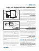
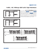
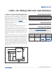
Using the high-speed QSPI interface with CPOL = 0 and
CPHA = 0, the MAX11101 supports a maximum f
SCLK
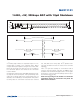
of 4.8MHz. Figure 11a shows the MAX11101 connected
to a QSPI master and Figure 11b shows the associated
interface timing.
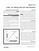
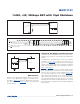
PIC16 with SSP Module and PIC17 Interface
The MAX11101 is compatible with a PIC16/PIC17 micro-
controller (FC) using the synchronous serial-port (SSP)
module.
To establish SPI communication, connect the controller
as shown in Figure 12a. Configure the PIC16/PIC17 as
system master, by initializing its synchronous serial-port
control register (SSPCON) and synchronous serial-port
status register (SSPSTAT) to the bit patterns shown in
Table 1 and Table 2.
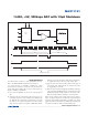
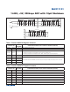
In SPI mode, the PIC16/PIC17 FC allows 8 bits of data
to be synchronously transmitted and received simulta-
neously. Three consecutive 8-bit readings (Figure 12b)
are necessary to obtain the entire 14-bit result from the
ADC. DOUT data transitions on the serial clock’s falling
edge and is clocked into the FC on SCLK’s rising edge.
The first 8-bit data stream contains all zeros. The second
8-bit data stream contains the MSB through D6. The third
8-bit data stream contains bits D5 through D0 followed
by S1 and S0.
Figure 11a. QSPI Connections
Figure 11b. QSPI Interface Timing Sequence (CPOL = CPHA = 0)
Figure 12a. SPI Interface Connection for a PIC16/PIC17
CS
QSPI
SCLK
DOUT
CS
SCK
MISO
V
DD
SS
MAX11101
DOUT*
CS
SCLK
*WHEN CS IS HIGH, DOUT = HIGH-Z
MSB
2016
D13 D12 D11
D10 D9 D8 D7
HIGH-Z
S1 S0
24
1214 86
D6 D3 D2 D1
LSB
D5 D4
END OF
ACQUISITION
D0
SCK
SDI
GND
PIC16/17
I/O
SCLK
DOUT
CS
V
DD
V
DD
MAX11101