
Datasheet

���������������������������������������������������������������� Maxim Integrated Products 14
MAX11101
14-Bit, +5V, 200ksps ADC with 10µA Shutdown
SPI and MICROWIRE Interfaces
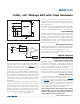
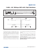
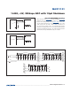
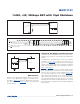
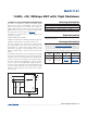
When using the SPI (Figure 10a) or MICROWIRE (Figure 10b)
interfaces, set CPOL = 0 and CPHA = 0. Conversion
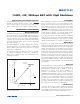
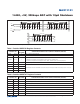
begins with a falling edge on CS (Figure 10c). Three con-
secutive 8-bit readings are necessary to obtain the entire
14-bit result from the ADC. DOUT data transitions on
the serial clock’s falling edge. The first 8-bit data stream
contains all leading zeros. The second 8-bit data stream
contains the MSB through D6. The third 8-bit data stream
contains D5 through D0 followed by S1 and S0.
Figure 10a. SPI Connections
Figure 10b. MICROWIRE Connections
Figure 10c. SPI/MICROWIRE Interface Timing Sequence (CPOL = CPHA =0)
SCLK
DOUT
I/O
SCK
MISO
SPI
V
DD
SS
MAX11101
CS
DOUT*
CS
SCLK
1ST BYTE READ
2ND BYTE READ
*WHEN CS IS HIGH, DOUT = HIGH-Z
MSB
HIGH-Z
3RD BYTE READ
LSB
S1 S0D5 D4 D3 D2 D1 D0
2420
1612
8
641
D13 D12 D11 D10 D9 D8 D7 D6 D5
000000 00
MAX11101
CS
MICROWIRE
SCLK
DOUT
I/O
SK
SI