
Datasheet


MAX1090/MAX1092
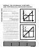
Signal-to-Noise Ratio
For a waveform perfectly reconstructed from digital
samples, signal-to-noise ratio (SNR) is the ratio of the
full-scale analog input (RMS value) to the RMS quanti-
zation error (residual error). The ideal theoretical mini-
mum analog-to-digital noise is caused by quantization
error only and results directly from the ADC’s resolution
(N bits):
SNR = (6.02 x N + 1.76)dB
In reality, there are other noise sources besides quanti-
zation noise, including thermal noise, reference noise,
clock jitter, etc. Therefore, SNR is computed by taking
the ratio of the RMS signal to the RMS noise, which
includes all spectral components minus the fundamen-
tal, the first five harmonics, and the DC offset.
Signal-to-Noise Plus Distortion
Signal-to-noise plus distortion (SINAD) is the ratio of the
fundamental input frequency’s RMS amplitude to the
RMS equivalent of all other ADC output signals.
SINAD (dB) = 20 x log (Signal
RMS
/ Noise
RMS
)
Effective Number of Bits
Effective number of bits (ENOB) indicates the global
accuracy of an ADC at a specific input frequency and
sampling rate. An ideal ADC’s error consists of quanti-
zation noise only. With an input range equal to the
ADC’s full-scale range, calculate the ENOB as follows:
ENOB = (SINAD - 1.76) / 6.02
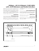
Total Harmonic Distortion
Total harmonic distortion (THD) is the ratio of the RMS
sum of the input signal’s first five harmonics to the fun-
damental itself. This is expressed as:
where V
1
is the fundamental amplitude, and V
2
through
V
5
are the amplitudes of the 2nd- through 5th-order
harmonics.
Spurious-Free Dynamic Range
Spurious-free dynamic range (SFDR) is the ratio of the
RMS amplitude of the fundamental (maximum signal
component) to the RMS value of the next-largest distor-
tion component.
THD VVVV V =× +++
20
2
2
3
2
4
2
5
2
1
log /
400ksps, +5V, 8-/4-Channel, 10-Bit ADCs
with +2.5V Reference and Parallel Interface
18 ______________________________________________________________________________________
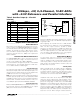
+3V
V
LOGIC
= +3V/+5V
GND
SUPPLIES
DGND+3V/+5VCOM
GND
4.7µF
0.1µF
V
DD
DIGITAL
CIRCUITRY
MAX1090
MAX1092
R* = 5Ω
*OPTIONAL
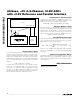
Figure 11. Power-Supply and Grounding Connections
Chip Information
TRANSISTOR COUNT: 5781