
Users Guide: Network Microcontroller Supplement User Manual

High-Speed Microcontroller User’s
Guide: Network Microcontroller
Supplement
93
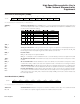
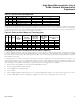
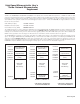
76543210
SFR FDh TF3 TR3 T3M SMOD_2 GATE C/T3 M1 M0
RW-0 RW-0 RW-0 RW-0 RW-0 RW-0 RW-0 RW-0
Timer 3 Control/Mode Register (T3CM)
R = Unrestricted read, W = Unrestricted write, -n = Value after reset
TF3
Bit 7
TR3
Bit 6
T3M
Bit 5
SMOD_2
Bit 4
GATE
Bit 3
C/T3
Bit 2
M1-0
Bits 1-0
Timer 3 overflow flag. This bit is set to 1 when timer 3 overflows its maximum count, as defined by the
current mode. It is cleared either by software or by the start of the timer 3 interrupt service routine. A
zero on this bit indicates that no timer 3 overflow has been detected.
Timer 3 run control. Setting this bit enables timer 3. Clearing this bit halts timer 3.
Timer 3 clock select. This bit controls the division of the system clock that drives timer 3. This bit has
no ef
fect on instruction cycle timing.
0 = Timer 3 uses a divide-by-12 of the crystal frequency.
1 = Timer 3 uses a divide-by-4 of the system clock frequency.
Serial port 2 baud-rate doubler enable. Setting this bit enables the serial baud-rate doubling function
in mode 1, 2, and 3 for serial por
t 2. A 0 disables the doubler.
Timer 3 gate control.
GATE = 0: Timer 3 clocks when TR3 is 1, regar
dless of INT3.
GATE = 1: Timer 3 clocks only when TR1 and INT3 are 1.
Counter/timer 1 select.
C/T3 = 0: Selects timer function with internal clock for timer 3.
C/T3 = 1: Selects counter function with input fr
om T3 when TR3 is 1.
T
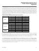
imer 3 mode-select bits 1 and 0.
M1
M0
TIMER MODE
0
0
Mode 0: 8-bit with 5-bit prescale
0
1
Mode 1: 16-bit with no prescale
1
0
Mode 2: 8-bit with autoreload
1
1
Mode 3: Timer 3 is halted, but its count is held.
Maxim Integrated