
Users Guide: Network Microcontroller Supplement User Manual

High-Speed Microcontroller User’s
Guide: Network Microcontroller
Supplement
90
76543210
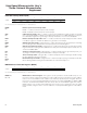
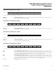
SFR F5h DPH3.7 DPH3.6 DPH3.5 DPH3.4 DPH3.3 DPH3.2 DPH3.1 DPH3.0
RW-0 RW-0 RW-0 RW-0 RW-0 RW-0 RW-0 RW-0
76543210
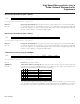
SFR F6h ID3 ID2 — — — — — —
RW-0 RW-0 R-1 R-1 R-1 R-1 R-1 R-1
7 6543210
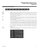
SFR F4h DPL3.7 DPL3.6 DPL3.5 DPL3.4 DPL3.3 DPL3.2 DPL3.1 DPL3.0
RW-0 RW-0 RW-0 RW-0 RW-0 RW-0 RW-0 RW-0
76543210
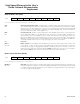
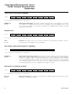
SFR F3h DPH2.7 DPH2.6 DPH2.5 DPH2.4 DPH2.3 DPH2.2 DPH2.1 DPH2.0
RW-0 RW-0 RW-0 RW-0 RW-0 RW-0 RW-0 RW-0
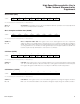
Data Pointer High Register 2 (DPH2)
R = Unrestricted read, W = Unrestricted write, -n = Value after reset
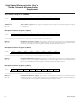
Data Pointer Low Register 3 (DPL3)
R = Unrestricted read, W = Unrestricted write, -n = Value after reset
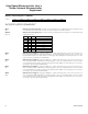
Data Pointer High Register 3 (DPH3)
R = Unrestricted read, W = Unrestricted write, -n = Value after reset
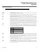
Data Pointer Select Register 1 (DPS1)
R = Unrestricted read, W = Unrestricted write, -n = Value after reset
DPH2.7–0
Bits 7–0
Data pointer high byte 2. This register is the high byte of auxiliary data pointer 2 and contains the mid-
dle-order byte of the 24-bit data address.
DPL3.7–0
Bits 7–0
Data pointer low byte 3. This register is the low byte of the auxiliary data pointer 3 and contains the
low-order byte of the 24-bit data address.
DPH3.7–0
Bits 7–0
Data pointer high byte 3. This register is the high byte of auxiliary data pointer 3 and contains the mid-
dle-order byte of the 24-bit data address.
ID3
Bit 7
ID2
Bit 6
Bits 5–0
Increment/decrement data pointer 3. This bit defines how the INC DPTR instruction functions in rela-
tion to data pointer 3 when it is selected by SEL1 and SEL bits (SEL1, SEL = 11). When ID3 is set to
logic 1, the INC DPTR instruction actually decrements the content of data pointer 3 by 1. When ID3 is
cleared to 0, the INC DPTR instruction increments the content of data pointer 3 by 1.
Increment/decrement data pointer 2. This bit defines how the INC DPTR instruction functions in rela-
tion to data pointer 2 when it is selected by SEL1 and SEL bits (SEL1, SEL = 10). When ID2 is set to
logic 1, the INC DPTR instruction actually decrements the content of data pointer 2 by 1. When ID2 is
cleared to 0, the INC DPTR instruction increments the content of data pointer 2 by 1.
Reserved. (Read returns all one’s.)
Maxim Integrated