
Users Guide: Network Microcontroller Supplement User Manual

High-Speed Microcontroller User’s
Guide: Network Microcontroller
Supplement
85
7 6543210
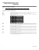
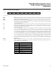
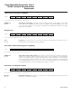
SFR E5h FPE RBF — BS4 BS3 BS2 BS1 BS0
RT-0 R-1 RT-0 RT-0 RT-0 RT-0 RT-0 RT-0
76543210
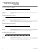
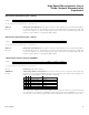
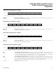
SFR E6h BCUD.7 BCUD.6 BCUD.5 BCUD.4 BCUD.3 BCUD.2 BCUD.1 BCUD.0
RW-0 RW-0 RW-0 RW-0 RW-0 RW-0 RW-0 RW-0
Ethernet Buffer Size (EBS)
R = Unrestricted read, T = Timed-access write only, -n = Value after reset
Buffer Control Unit Data (BCUD)
R = Unrestricted read, W = Unrestricted write, -n = Value after reset
FPE
Bit 7
RBF
Bit 6
Bit 5
BS4–0
Bits 4–0
Flush filter failed-packet enable. Setting this bit to 1 enables the BCU to abort the current receive oper-
ation and flush data received for the current frame from the receive buffer if the packet fails the address
filtering. The receive interrupt flag is not set and no receive interrupt is generated. Clearing this bit to 0
allows the BCU to receive all packets, regardless of its address-filtering result. This bit is overridden if
the receive-all bit in the MAC control register is set.
Receive buffer full. This bit is a read-only bit and is set by hardware when there is no open page in the
receive buffer. When RBF is set, the BCU ignores any new frame received by the MAC. Under this con-
dition, the BCU has to acknowledge the receive status word, but the receive data buffer and receive
FIFO are not updated, the receive interrupt flag is not set, and no receive interrupt is generated. The
RBF bit is set when the BCU abor
ts an incoming frame that overflows the receive buffer. The RBF bit is
cleared by hardware when there are enough open pages (>4) in the receive buffer.
Reserved.
Buffer size bits. The BS4:0 bits can be programmed to any value n between 0 and 31, inclusive. The
receive buffer occupies the first n pages of the 8kB memory, while the transmit buf
fer occupies the
remaining (32–n) pages. Changing the BS4:0 bits automatically flushes the contents of the receive
buffer and receive FIFO. Note that when BS4:0 = 00000b (default value), there are no receive buffers.
When BS4:0 = 00001b, this is the first receive buffer and the rest are transmit buffers.
BCUD.7–0
Bits 7–0
BCU data. This register serves as the BCU data register for packet transmit and receive operation. For
transmit operation, the 11-bit byte count and the starting page address of the transmit packet are loaded
to the BCU through the BCUD register. For receive operation, the page information of the current pack-
et can be read by the BCUD register.
Maxim Integrated