
Users Guide: Network Microcontroller Supplement User Manual

High-Speed Microcontroller User’s
Guide: Network Microcontroller
Supplement
70
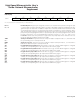
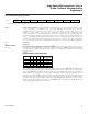
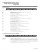
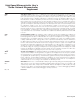
Status Register (STATUS)
R = Unrestricted read, -n = Value after reset
7 6543210
SFR C5 PIP HIP LIP — SPTA1 SPRA1 SPTA0 SPRA0
R-0 R-0 R-0 — R-0 R-0 R-0 R-0
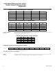
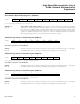
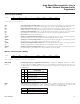
Memory Control Register (MCON)
R = Unrestricted read, T = Timed-access write only, -n = Value after reset
PIP
Bit 7
HIP
Bit 6
LIP
Bit 5
Bit 4
SPTA1
Bit 3
SPRA1
Bit 2
SPTA0
Bit 1
SPRA0
Bit 0
Power-fail priority interrupt status. When set, this bit indicates that software is currently servicing a
power-fail interrupt. It is cleared when the program executes the corresponding RETI instruction.
High-priority interrupt status. When set, this bit indicates that software is currently servicing a high-
priority interrupt. It is cleared when the program executes the corresponding RETI instruction.
Low-priority interrupt status. When set, this bit indicates that software is currently servicing a low-pri-
ority interrupt. It is cleared when the program executes the corresponding RETI instruction.
Reserved. Read value is indeterminate.
Serial port 1 transmit activity monitor. When set, this bit indicates that data is currently being trans-
mitted by serial port 1. It is cleared when the internal hardware sets the TI_1 bit.
Serial port 1 receive activity monitor. When set, this bit indicates that data is currently being received
by serial por
t 1. It is cleared when the internal hardware sets the RI_1 bit.
Serial port 0 transmit activity monitor
. When set, this bit indicates that data is currently being trans-
mitted by serial port 0. It is cleared when the internal hardware sets the TI_0 bit.
Serial port 0 receive activity monitor. When set, this bit indicates that data is currently being received
by serial port 0. It is cleared when the internal hardware sets the RI_0 bit.
76543210
SFR C6h IDM1 IDM0 CMA — PDCE3 PDCE2 PDCE1 PDCE0
RT-0 RT-0 RT-0 R-1 RT-0 RT-0 RT-0 RT-0
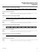
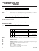
IDM1, IDM0
Bits 7-6
Internal data memory configuration and memory. The IDM1 and IDM0 bits establish the address
location of the internal MOVX SRAM memory. Use of the SRAM for extended stack memory (SA = 1 in
the ACON SFR) is not disrupted by the memory relocation assignment. These bits do not exist in the
DS80C410/411.
IDM1
IDM0
INTERNAL SRAM MEMORY
LOCATION (HEX)
00
00DC00–00FFFF (1kB = 00DC00–00DFFF,
8kB = 00E000–00FFFF)
01
000000–0023FF (8kB = 000000–001FFF,
1kB = 002000–0023FF)
10
FFDC00–FFFFFF (1kB = FFDC00–FFDFFF,
8kB = FFE000–FFFFFF)
11
Reserved, trying to write 11b does not change
the previous setting.
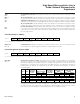
CMA
Bit 5
CAN data memory assignment. The CMA bit provides a software mechanism for moving the data
memory blocks associated with the CAN controller. The 256 bytes of data memory can be located at
one of the two following address locations. This bit does not exist in the DS80C410/411.
CMA CAN MEMORY LOCATION (HEX)
0 00DB00–00DBFF - Reset default
1 FFDB00–FFDBFF
Maxim Integrated