
Users Guide: Network Microcontroller Supplement User Manual

High-Speed Microcontroller User’s
Guide: Network Microcontroller
Supplement
63
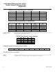
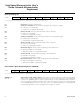
Peripheral Chip-Enable Boundaries—DS80C400
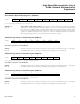
Peripheral Chip-Enable Boundaries—DS80C410/411
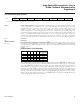
CE4–CE7 Chip-Enable Function Selection
P6CNT.2–0
P6.3 P6.2 P6.1 P6.0
000 I/O I/O I/O I/O
100 I/O I/O I/O CE4
101 I/O I/O CE5 CE4
110 I/O CE6 CE5 CE4
111 CE7 CE6 CE5 CE4
P6CNT.5–3
PCE0 PCE1 PCE2 PCE3
000 —- — 64kB–96kB 96kB–128kB
001 64kB–128kB 128kB–256kB 256kB–384kB 384kB–512kB
010 64kB–256kB 256kB–512kB 512kB–768kB 768kB–1MB
011 64kB–512kB 512kB–1MB 1MB–1.5MB 1.5MB–2MB
100 64kB–1MB 1MB–2MB 2MB–3MB 3MB–4MB
P6CNT.5–3
PCE0 PCE1 PCE2 PCE3
000 0–32kB 32kB–64kB 64kB–96kB 96kB–128kB
001 0–128kB 128kB–256kB 256kB–384kB 384kB–512kB
010 0–256kB 256kB–512kB 512kB–768kB 768kB–1MB
011 0–512kB 512kB–1MB 1MB–1.5MB 1.5MB–2MB
100 0–1MB 1MB–2MB 2MB–3MB 3MB–4MB
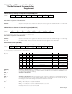
P6CNT.2–P6CNT.0
Bits 2–0
Port pin P6.3–P6.0 configuration control bits. P6CNT.2-0 determine whether specific P6 pins function
as program chip-enable signals or as I/O.
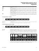
C0M6C
Bits 7–0
Operation of the bits in this register are identical to those found in the CAN 0 message 1 control regis-
ter (C0M1C: ABh). Consult the description of that register for more information.
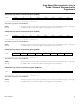
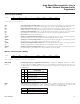
CAN 0 Message Center 6 Control Register (C0M6C)
76543210
SFR B3h MSRDY ETI ERI INTRQ EXTRQ MTRQ ROW/TIH DTUP
RW-0 RW-0 RW-0 RW-0 RC-0 R*-0 R*-0 R*-0
R = Unrestricted read, C = Clear only, * = See description, -n = Value after reset
This SFR is not present on the DS80C411.
Maxim Integrated