
Users Guide: Network Microcontroller Supplement User Manual

High-Speed Microcontroller User’s
Guide: Network Microcontroller
Supplement
38
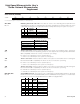
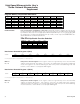
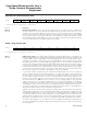
Serial Port 0 Control (SCON0)
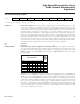
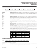
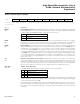
Serial Data Buffer 0 (SBUF0)
7 6543210
SFR 98h SM0/FE_0 SM1_0 SM2_0 REN_0 TB8_0 RB8_0 TI_0 RI_0
RW-0 RW-0 RW-0 RW-0 RW-0 RW-0 RW-0 RW-0
R = Unrestricted read, W = Unrestricted write, -n = Value after reset
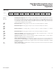
SM0/FE_0
Bit 7
SM1_0
Bit 6
SM2_0
Bit 5
REN_0
Bit 4
TB8_0
Bit 3
RB8_0
Bit 2
TI_0
Bit 1
RI_0
Bit 0
Serial port 0 mode bit 0. (When SMOD0 is logic 0.) When SMOD0 is logic 1, it is the framing error flag
that is set upon detection of an invalid stop bit and must be cleared by software. When SMOD0 is set,
modification of this bit has no effect on the serial mode setting.
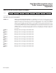
Serial port 0 mode bit 1.
Serial port 0 mode bit 2. Setting of this bit in mode 1 ignores reception if an invalid stop bit is
detected. Setting this bit in mode 2 or 3 enables multipr
ocessor communications. This prevents the RI_0
bit from being set, and interrupt being asserted, if the 9th bit received is 0.
Receiver enable. This bit enable/disables the serial port 0 receiver shift register.
0 = Serial port 0 reception disabled.
1 = Serial port 0 r
eceiver enabled (modes 1, 2, and 3). Initiate synchronous reception (mode 0).
9th transmission bit state. This bit defines the state of the 9th transmission bit in serial port 0 modes
2 and 3.
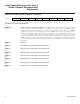
9th received bit state. This bit identifies that state of the 9th reception bit of received data in ser
-
ial port 0 modes 2 and 3. When SM2_0 = 0, RB8_0 is the state of the stop bit in mode 1. RB8_0 is not
used in mode 0.
Transmitter interrupt flag. This bit indicates that data in the serial port 0 buffer has been completely
shifted out. In serial por
t mode 0, TI_0 is set at the end of the 8th data bit. In all other modes, this bit is
set at the end of the last data bit. This bit must be cleared by software.
Receiver interrupt flag. This bit indicates that a byte of data has been received in the serial port 0
buffer. In serial port mode 0, RI_0 is set at the end of the 8th bit. In serial port mode 1, RI_0 is set after
the last sample of the incoming stop bit subject to the state of SM2_0. In modes 2 and 3, RI_0 is set after
the last sample of RB8_0. This bit must be cleared by softwar
e.
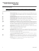
MODE
SM2
SM1
SM0
FUNCTION
LENGTH
PERIOD
000
0
Synchronous 8 bits 12 t
CLK
010
0
Synchronous 8 bits 4 t
CLK
1x1
0
Asynchronous 10 bits Timer 1 or 2
200
1
Asynchronous 11 bits 64 t
CLK
(SMOD_0 = 0)
200
1
Asynchronous 11 bits 32 t
CLK
(SMOD_0 = 1)
210
1
Asynchronous (MP)
11 bits 64 t
CLK
(SMOD_0 = 0)
210
1
Asynchronous (MP)
11 bits 34 t
CLK
(SMOD_0 = 1)
301
1
Asynchronous 11 bits Timer 1 or 2
311
1
Asynchronous (MP)
11 bits Timer 1 or 2
76543210
SFR 99h SBUF0.7 SBUF0.6 SBUF0.5 SBUF0.4 SBUF0.3 SBUF0.2 SBUF0.1 SBUF0.0
RW-0 RW-0 RW-0 RW-0 RW-0 RW-0 RW-0 RW-0
R = Unrestricted read, W = Unrestricted write, -n = Value after reset
SBUF0.7–0
Bits 7–0
Serial data buffer 0. Data for serial port 0 is read from or written to this location. The serial transmit and
receive buffers are separate registers, but both are addressed at this location.
Maxim Integrated