
Users Guide: Network Microcontroller Supplement User Manual

High-Speed Microcontroller User’s
Guide: Network Microcontroller
Supplement
31
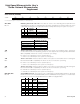
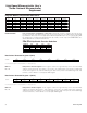
Clock Control (CKCON)
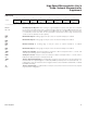
WD1, WD0
Bits 7-6
Watchdog timer mode select 1-0. These bits are used to select watchdog timeout periods for the
watchdog timer function. The watchdog timer generates interrupt timeout at this periodic rate, when
enabled. All watchdog timer reset timeouts follow the interrupt timeouts by 512 system clock cycles.
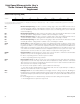
The system clock relates to the external clock as follows:
CLOCK MODE
EXTERNAL CLOCKS PER
SYSTEM CLOCK
Frequency multiplier (4x) 0.25
Frequency multiplier (2x) 0.5
Divide-by-4 1
Power-management mode 256
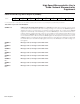
WD1
WD0
INTERRUPT
TIMEOUT
RESET TIMEOUT
0 02
17
system clocks
2
17
+ 512 system clocks
012
20
system clocks
2
20
+ 512 system clocks
102
23
system clocks
2
23
+ 512 system clocks
1 12
26
system clocks
2
26
+ 512 system clocks
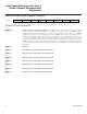
7 6543210
SFR 8Eh WD1 WD0 T2M T1M T0M MD2 MD1 MD0
RW-0 RW-0 RW-0 RW-0 RW-0 RW-0 RW-0 RW-1
R = Unrestricted read, W = Unrestricted write, -n = Value after reset
T2M
Bit 5
T1M
Bit 4
T0M
Bit 3
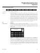
MD2, MD1, MD0
Bits 2-0
Timer 2 clock select. This bit controls the division of the system clock that drives timer 2. This bit has
no effect when the timer is in baud-rate generator or clock output modes. Clearing this bit to 0 maintains
8051 compatibility. This bit has no effect on instruction cycle timing.
0 = Timer 2 uses a divide-by-12 of the crystal frequency.
1 = Timer 2 uses a divide-by-4 of the system clock frequency.
Timer 1 clock select. This bit controls the division of the system clock that drives timer 1. Clearing this
bit to 0 maintains 8051 compatibility. This bit has no effect on instruction cycle timing.
0 = Timer 1 uses a divide-by-12 of the crystal frequency.
1 = Timer 1 uses a divide-by-4 of the system clock frequency.
Timer 0 clock select. This bit controls the division of the system clock that drives timer 0. Clearing this
bit to 0 maintains 8051 compatibility. This bit has no effect on instruction cycle timing.
0
= Timer 0 uses a divide-by-12 of the crystal frequency.
1 = Timer 0 uses a divide-by-4 of the system clock frequency.
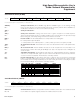
Stretch MOVX select 2-0. These bits select the control timing for external MOVX instructions. All internal
MOVX instructions to the internal MOVX SRAM, as well as CAN 0 data memory registers, occur at t
he fastest
two-machine cycle rate. The internal MOVX rate to the SRAM is not programmable.
MD2 MD1 MD0
STRETCH
VALUE
MOVX DURATION
0 0 0 0 2 machine cycles
001 1
3 machine cycles
(reset default)
0 1 0 2 4 machine cycles
0 1 1 3 5 machine cycles
1 0 0 4 9 machine cycles
1 0 1 5 10 machine cycles
1 1 0 6 11 machine cycles
1 1 1 7 12 machine cycles
Maxim Integrated