
Users Guide: Network Microcontroller Supplement User Manual

High-Speed Microcontroller User’s
Guide: Network Microcontroller
Supplement
29
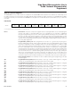
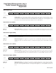
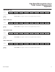
Timer Mode Control (TMOD)
7 6543210
SFR 89h GATE C/T M1 M0 GATE C/T M1 M0
RW-0 RW-0 RW-0 RW-0 RW-0 RW-0 RW-0 RW-0
R = Unrestricted read, W = Unrestricted write, -n = Value after reset
GATE
Bit 7
C/T
Bit 6
M1, M0
Bits 5-4
GATE
Bit 3
C/T
Bit 2
M1, M0
Bits 1-0
Timer 1 gate control. This bit enables/disables the ability of timer 1 to increment.
0 = Timer 1 clocks when TR1 = 1, regardless of the state of INT1.
1 = Timer 1 clocks only when TR1 = 1 and INT1 = 1.
Timer 1 counter/timer select.
0 = Timer 1 is incremented by internal clocks.
1 = Timer 1 is incremented by pulses on T1 when TR1 (TCON.6) is 1.
Timer 1 mode select. These bits select the operating mode of timer 1.
M1 M0 Mode
0 0 Mode 0: 8 bits with 5-bit prescale
0 1 Mode 1: 16 bits
1
0 Mode 2: 8 bits with autoreload
1 1 Mode 3: Timer 1 is halted but holds its count
Timer 0 gate control. This bit enables/disables the ability of timer 0 to increment.
0 = Timer 0 clocks when TR0 = 1, regardless of the state of INT0.
1 = Timer 0 clocks only when TR0 = 1 and INT0 = 1.
Timer 0 counter/timer select.
0
= Timer incremented by internal clocks.
1 = Timer 0 is incremented by pulses on T0 when TR0 (TCON.4) is 1.
Timer 0 mode select. These bits select the operating mode of timer 0. When timer 0 is in mode 3, TL0
is started/stopped by TR0 and TH0 is started/stopped by TR1. Run control from timer 1 is then provid-
ed through the timer 1 mode selection.
M1 M0 Mode
0
0 Mode 0: 8 bits with 5-bit prescale
0 1
Mode 1: 16 bits
1 0 Mode 2: 8 bits with autoreload
1 1 Mode 3: Two 8-bit timers for timer 0; timer 1 is stopped.
Maxim Integrated