
Users Guide: Network Microcontroller Supplement User Manual

High-Speed Microcontroller User’s
Guide: Network Microcontroller
Supplement
28
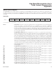
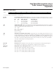
Timer/Counter Control (TCON)
TF1
Bit 7
TR1
Bit 6
TF0
Bit 5
TR0
Bit 4
IE1
Bit 3
IT1
Bit 2
IE0
Bit 1
IT0
Bit 0
Timer 1 overflow flag. This bit indicates when timer 1 overflows its maximum count as defined
by the current mode. This bit can be cleared by software and is automatically cleared when the CPU
vectors to the timer 1 interrupt service routine.
0 = No timer 1 overflow has been detected.
1 = Timer 1 has overflowed its maximum count.
Timer 1 run control. This bit enables/disables the operation of timer 1.
0 = Timer 1 is halted.
1 = Timer 1 is enabled.
Timer 0 overflow flag. This bit indicates when timer 0 overflows its maximum count as defined
by the current mode. This bit can be cleared by software and is automatically cleared when the CPU
vectors to the timer 0 interrupt service r
outine or by software.
0 = No timer 0 overflow has been detected.
1 = Timer 0 has overflowed its maximum count.
Timer 0 run control. This bit enables/disables the operation of timer 0.
0 = Timer 0 is halted.
1 = Timer 0 is enabled.
Interrupt 1 edge detect. This bit is set when an edge/level of the type defined by IT1 is
detected. If IT1 = 1, this bit remains set until cleared in software or until the start of the external interrupt
1 ser
vice routine. If IT1 = 0, this bit inversely reflects the state of the INT1 pin.
Interrupt 1 type select. This bit selects whether the INT1 pin detects edge- or level-triggered
interrupts.
0 = INT1 is level triggered.
1 = INT1 is edge triggered.
Interrupt 0 edge detect. This bit is set when an edge/level of the type defined by IT0 is
detected. If IT0 = 1, this bit r
emains set until clear
ed in softwar
e or the star
t of the exter
nal interrupt 0
service r
outine. If IT0 = 0, this bit inversely r
eflects the state of the INT0 pin.
Interrupt 0 type select. This bit selects whether the INT0 pin detects edge- or level-trigger
ed
interrupts.
0
= INT0 is level trigger
ed.
1
= INT0 is edge triggered.
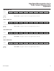
7 6543210
SFR 88h TF1 TR1 TF0 TR0 IE1 IT1 IE0 IT0
RW-0 RW-0 RW-0 RW-0 RW-0 RW-0 RW-0 RW-0
R = Unrestricted read, W = Unrestricted write, -n = Value after reset
Maxim Integrated