
Users Guide: Network Microcontroller Supplement User Manual

High-Speed Microcontroller User’s
Guide: Network Microcontroller
Supplement
165
SECTION 20: ARITHMETIC ACCELERATOR
The DS80C400 incorporates an arithmetic accelerator that performs 32-bit and 16-bit calculations while maintaining 8051 software
compatibility. Math operations are performed by sequentially loading three special registers. The mathematical operation is determined
by the sequence in which three dedicated SFRs (MA, MB, and MCNT0) are accessed, eliminating the need for a special step to choose
the operation. The arithmetic accelerator has four functions: multiply, divide, shift right/left, and normalize. The normalize function facil-
itates the conversion of 4-byte unsigned binary integers into floating point format. An integral 40-bit accumulator, described later, sup-
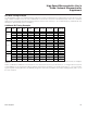
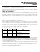
ports multiply-and-add and divide-and-add operations. Table 20-1 shows the operations supported by the math accelerator and their
time of execution.
Table 20-1. Arithmetic Accelerator Execution Times
The following is a brief summary of the bits and registers used in conjunction with arithmetic acceleration operations. Please consult
the SFR listing in Section 4 for a complete description of all these registers.
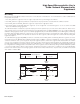
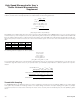
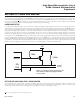
The following procedures illustrate how to use the arithmetic accelerator. The MA and MB registers must be loaded and read in the
order shown for proper operation, although accesses to any other registers can be performed between accesses to the MA or MB
registers. An access to the MA, MB, or MC registers out of sequence corrupts the operation, requiring the software to clear the MST
bit to restart the math accelerator-state machine.
OPERATION RESULT EXECUTION TIME
32-bit by 16-bit divide 32-bit quotient, 16-bit remainder 36 t
CLCL
16-bit by 16-bit divide 16-bit quotient, 16-bit remainder 24 t
CLCL
16-bit by 16-bit multiply 32-bit product 24 t
CLCL
32-bit shift left/right 32-bit result 36 t
CLCL
32-bit normalize 32-bit mantissa, 5-bit exponent 36 t
CLCL
LSHIFT
MCNT0.7
CSE
MCNT0.6
SCE
MCNT0.5
MAS4–0
MCNT0.4–0
MST
MCNT1.7
MOF
MCNT1.6
SCB
MCNT1.5
CLM
MCNT1.4
MA
MA.7–0
MB
MB.7–0
MC
MC.7–0
Left shift. This bit determines whether shift operations proceed from LSB to MSB or vice-versa.
Circular shift enable. This bit determines whether shift operations wrap between the LSB and MSB.
Shift carry enable. This bit determines whether the arithmetic accelerator carry bit is included in the
shift process.
Multiplier register shift bits. When performing a shift operation, these bits determine how many shifts
to perform. Following a nor
malize operation, these bits indicate the number shifts performed.
Multiply/accumulate status flag. This bit serves as a busy flag for the arithmetic accumulator operations.
Multiply overflow flag. This bit is set when a divide-by-0 is attempted or when the result of a 16-bit by
16-bit multiplication exceeds FFFFh.
Shift carry bit. This bit serves as the carry bit during arithmetic accelerator shift operations when SCE
= 1. This bit must be clear
ed or set by software as desired before each new shift operation.
Clear math accelerator registers. Setting this bit clears the MA, MB, and MC registers.
Multiplier A register. This register is used as both a source and result register for various arithmetic
accelerator functions.
Multiplier B register
. This register is used as both a source and result r
egister for various arithmetic
accelerator functions.
Multiplier C register. This register serves as the 40-bit accumulator of the arithmetic accelerator.
Maxim Integrated