
Users Guide: Network Microcontroller Supplement User Manual

High-Speed Microcontroller User’s
Guide: Network Microcontroller
Supplement
161
Bus-Off/Bus-Off Recovery and Error Counter Operation
The CAN module contains two SFRs that allow software to monitor and modify (under controlled conditions) the error counts associat-
ed with the transmit-error and receive-error counters in each CAN module. These registers can be read at any time. Writing the CAN
transmit-error counter registers updates both the transmit-error counter registers and the receive-error counter registers with the same
value. Details are given in the SFR description of these registers. These counters are incremented or decremented according to CAN
specification version 2.0B, summarized in the following rules. The error counters are initialized by a CRST = 1 or a system reset to 00h.
The error counters remain unchanged when the CAN module enters and exits from a low-power mode through the SIESTA or PDE bit.
Changes to the error counters are performed according to the following rules. This level of detail is not necessary for the average CAN
user, and full information is provided in the CAN 2.0B specification. More than one rule can apply to a given message.
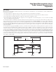
A node is error active when the transmit-error and receive-error counters are less than 128. When in an error-active state, an error con-
dition causes the node to send an error frame on the bus. A node is error-passive when the transmit-error count equals or exceeds 128,
or when the receive-error count equals or exceeds 128. An error-passive node does not transmit an error frame on the bus. An error-
passive node becomes error-active again when both the transmit-error and receive-error counts are less than or equal to 127.
A node is bus off when the transmit-error count is greater than or equal to 256. A bus-off node becomes error active (no longer bus off)
when its error counters are both set to 0 and after 128 occurrences of 11 consecutive recessive bits have been monitored on the bus.
After exceeding the error-passive limit (128), the receive-error counter is not increased further. When a message is received correctly,
the counter is set again to a value between 119 and 127 (compare with CAN 2.0B specification). After reaching bus-off status, the trans-
mit-error counter is undefined while the receive-error counter is cleared and changes its function. The receive-error counter is incre-
mented after every 11 consecutive recessive bits on the bus. These 11 bits correspond to the gap between two messages on the bus.
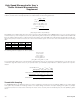
If the receive-error counter reaches count = 128 following the bus-off recovery sequence, the CAN module changes automatically back
to the status of bus on and then sets SWINT = 1. After setting SWINT, all internal flags of the CAN module are reset and the error coun-
ters are cleared. A recovery from a bus-off condition does not alter the previously programmed MOVX memory values or SFR registers,
apart from the transmit-error and receive-error SFR registers and the error conditions displayed in CAN status register. The bus timing
remains as previously programmed.
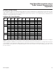
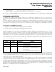
CONDITION EFFECT ON ERROR COUNTER S
Err or detect ed by rec e iver , un less th e det ec ted error wa s a bit error during th e
se nd i ng o f an a ctiv e error f lag or an ov er l oad f l ag.
Re c e iv e-error counter i ncrem e nt ed by 1.
Re c e iv er dete cts a d o m in a nt b it a s t h e fir st bit aft er se nding an error fl ag. Re c e ive- error cou nt er increm e nt ed b y 8.
Trans mi t t er s end s an error f lag .
Note: The trans mi t-error count doe s not ch a nge if:
• Th e tran smi t t er i s error pa ss ive and detects a n ac k n owl edg ement error becau se
of n ot det ec t i n
g a d om in a n t ack n ow led ge a nd does n ot dete ct a do m i n a nt b i t
whil e s e nding its p a ss i v e error flag .
• If t h e transmitter s e nd s an error f lag beca u se a s t uf f error occurred dur ing
arbitratio n , a
nd ha s be en s e n t as r eces si ve , but moni t ored as do m in a nt .
Trans mi t-error counter i n creme nt ed by 8.
Trans mi t t er detect s a b it error wh il e s e nd i ng an act ive error flag or an o verl o ad f l ag. Tran s mi t-error counter i n creme nt ed b y 8 .
Re c e iv er dete cts a bit error whil e s e nd i ng an act ive error flag or an o verlo ad fl ag. Rec e iv e-error cou nt er increm e nt ed b y 8.
Node detect s th e 1 4t h consec ut ive domina nt b it (in c ase o f an a ctiv e error f lag or
an ov er l o ad f l ag), or d etect s the 8t h cons e c utiv e do m in a nt b it fo ll owi ng a pa ssi ve
error flag, or aft er a sequ en c e of additi o n al eigh t co ns e c ut iv e domi n a nt b i t s.
Trans mi t-error counter i n creme nt ed by 8.
Re c e iv e-error counter i ncrem e nt ed by 8.
Me ssage is su c c ess f ully tr ans mitted (ac k n ow led ge rece ived and n o error unti l e nd
of frame i s c o mpl et e).
Trans mi t-error counter is decrem e nt ed by 1
(un le ss i t w a s alread y 0).
A m e ss ag e ha s be en su c c ess f ully re ceived (recept i on with ou t error up to t h e
ac k n ow l edge s l o t a nd th e s u c cess f ul s e nd i ng of the a c kn ow led ge bit), a nd th e
receiv e-error count wa s betw e en 1 a nd 12 7.
Re c e iv e-error counter decrement ed by 1.
A m e ss ag e ha s be en su c c ess f ully re ceived (recept i on with ou t error up to t h e
ac k n ow l edge s l o t a nd th e s u c cess f ul s e nd i ng of the a c kn ow led ge bit), a nd th e
receiv e-error count wa s greater than 1 27 .
Re c e iv e-error counter is s e t to a val u e
between 1 1 9 and 1 27.
Maxim Integrated