
Users Guide: Network Microcontroller Supplement User Manual

High-Speed Microcontroller User’s
Guide: Network Microcontroller
Supplement
128
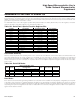
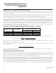
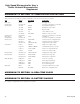
Table 12-6. Relationship Between External Crystal Frequency and Timer 2
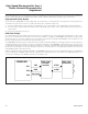
When using timer 2 to generate baud rates, the formula is as follows. Note that the reload value is a 16-bit number as compared with
timer 1, which uses only 8 bits. A second equation is provided here so that the timer 2 reload value can be calculated for a given baud
rate:
Timer 2 input clock frequency can be found in Table 12-6, and RCAP2H, RCAP2L is the user-assigned timer 2 reload value.
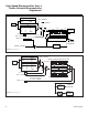
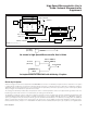
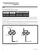
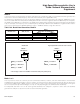
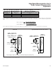
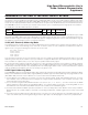
Figure 12-3. Serial Port Modes 1, 3 Block Diagram Change
Mode baud rate
Timer Input Clock
,
13
1
16
2
=×
, ,
,
Frequency
RCAP H RCAP L
RCAP H R
65 536 2 2
2
−
CCAP L
Timer Input Clock Frequ
265536
2
,=−
eency
Baud Rate16 ×
OSCILLATOR CYCLES
PER MACHINE CYCLE
PMR REGISTER BITS
4X/2X, CD1, CD0
TIMER 2 INPUT CLOCK FREQUENCY
BAUD-RATE GENERATOR MODE (RCLK or TCLK = 1)
1 (4x mode) 100 OSC / 2
2 (2x mode) 000 OSC / 2
4 (default) X01, X10 OSC / 2
1024 (PMM) X11 OSC / 1024
DS80C400 High-Speed Microcontroller User's Guide
1
This change is due to the addition of the third serial port (serial port 2).
DIVIDE-
BY-2
SMOD_x
(x = 0, 1, or 2)
1
TIMER 2
OVERFLOW
TIMER 1 OVERFLOW
(SERIAL PORT 0 or 1)
or
TIMER 3 OVERFLOW
1
(SERIAL PORT 2)
AVAILABLE TO SERIAL
PORT 0 ONLY
10
10
10
TCLK =
T2CON.4
RCLK =
T2CON.5
DIVIDE-
BY-2
SMOD_x
TIMER 2
OVERFLOW
TIMER 1 OVERFLOW
(SERIAL PORT 0 or 1)
AVAILABLE TO SERIAL
PORT 0 ONLY
10
10
10
TCLK =
T2CON.4
RCLK =
T2CON.5
Maxim Integrated