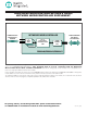
HIGH-SPEED MICROCONTROLLER USER’S GUIDE: NETWORK MICROCONTROLLER SUPPLEMENT COMMUNICATE WITH NEW AND LEGACY EQUIPMENT NETWORKED MICROCONTROLLER x3 SERIAL UARTs 8051 µC WITH TCP/IPv4/6 NETWORK STACK IN ROM REMOTE MONITORING AND CONTROL VIA THE NETWORK 10/100 ETHERNET MAC DS80C400/DS80C410/DS80C411 This document is provided as a supplement to the High-Speed Microcontroller User’s Guide, covering new or modified features specific to the DS80C400/DS80C410/DS80C411.
High-Speed Microcontroller User’s Guide: Network Microcontroller Supplement TABLE OF CONTENTS ADDENDUM TO SECTION 1: INTRODUCTION 14 Features . . . . . . . . . . . . . . . . . . . . . . . . . . . . . . . . . . . . . . . . . . . . . . . . . . . . . . . . . . . . . . . . . . .14 ADDENDUM TO SECTION 2: ORDERING INFORMATION 15 Refer to the device-specific data sheet(s) for more information. ADDENDUM TO SECTION 3: ARCHITECTURE 15 CPU Core and CPU Registers . . . . . . . . . . . . . . . . . . . . . . . .
High-Speed Microcontroller User’s Guide: Network Microcontroller Supplement Data Pointer Extended Register 1 (DPX1) . . . . . . . . . . . . . . . . . . . . . . . . . . . . . . . . . . . . . .35 CAN 0 Receive Message Stored Register 0 (C0RMS0) . . . . . . . . . . . . . . . . . . . . . . . . . . .36 CAN 0 Receive Message Stored Register 1 (C0RMS1) . . . . . . . . . . . . . . . . . . . . . . . . . . .37 Serial Port 0 Control (SCON0) . . . . . . . . . . . . . . . . . . . . . . . . . . . . . . . . . . . . . . .
High-Speed Microcontroller User’s Guide: Network Microcontroller Supplement CAN 0 Message Center 15 Control Register (C0M15C) . . . . . . . . . . . . . . . . . . . . . . . . . . .67 Serial Port Control (SCON1) . . . . . . . . . . . . . . . . . . . . . . . . . . . . . . . . . . . . . . . . . . . . . . . . .67 Serial Data Buffer 1 (SBUF1) . . . . . . . . . . . . . . . . . . . . . . . . . . . . . . . . . . . . . . . . . . . . . . . .68 Power-Management Register (PMR) . . . . . . . . . . . . . . . . . . . . .
High-Speed Microcontroller User’s Guide: Network Microcontroller Supplement B Register (B) . . . . . . . . . . . . . . . . . . . . . . . . . . . . . . . . . . . . . . . . . . . . . . . . . . . . . . . . . . . .89 Slave Address Mask Enable Register 2 (SADEN2) . . . . . . . . . . . . . . . . . . . . . . . . . . . . . . .89 Data Pointer Low Register 2 (DPL2) . . . . . . . . . . . . . . . . . . . . . . . . . . . . . . . . . . . . . . . . . .89 Data Pointer High Register 2 (DPH2) . . . . . . . . . . . . . . . .
High-Speed Microcontroller User’s Guide: Network Microcontroller Supplement Stop Mode . . . . . . . . . . . . . . . . . . . . . . . . . . . . . . . . . . . . . . . . . . . . . . . . . . . . . . . . . . . . . . . . .111 Pin States in Idle or Stop Mode . . . . . . . . . . . . . . . . . . . . . . . . . . . . . . . . . . . . . . . . . . . . . . . . .111 Switching Between Clock Sources . . . . . . . . . . . . . . . . . . . . . . . . . . . . . . . . . . . . . . . . . . . . . . .
High-Speed Microcontroller User’s Guide: Network Microcontroller Supplement ADDENDUM TO SECTION 15: BATTERY BACKUP 129 Refer to the High-Speed Microcontroller User’s Guide. Not applicable to the DS80C400/410/411. ADDENDUM TO SECTION 16: INSTRUCTION SET DETAILS 130 16-Bit (8051 Standard) Addressing Mode . . . . . . . . . . . . . . . . . . . . . . . . . . . . . . . . . . . . . . . . .130 24-Bit Paged Addressing Mode . . . . . . . . . . . . . . . . . . . . . . . . . . . . . . . . . . . . . . . . . . . .
High-Speed Microcontroller User’s Guide: Network Microcontroller Supplement CAN 0 Message Center y Format Register (C0MyF) . . . . . . . . . . . . . . . . . . . . . . . . . . . . . .146 CAN 0 Message Center y Data Byte 0 (C0MyD0) . . . . . . . . . . . . . . . . . . . . . . . . . . . . . . . .147 CAN 0 Message Center y Data Byte 1 (C0MyD1) . . . . . . . . . . . . . . . . . . . . . . . . . . . . . . . .147 CAN 0 Message Center y Data Byte 2 (C0MyD2) . . . . . . . . . . . . . . . . . . . . . . . . . . . . . .
High-Speed Microcontroller User’s Guide: Network Microcontroller Supplement Setting Up and Using the 1-Wire Master . . . . . . . . . . . . . . . . . . . . . . . . . . . . . . . . . . . . . . . . . .168 Setting Up the 1-Wire Master . . . . . . . . . . . . . . . . . . . . . . . . . . . . . . . . . . . . . . . . . . . . . . . .169 Sending a 1-Wire Reset . . . . . . . . . . . . . . . . . . . . . . . . . . . . . . . . . . . . . . . . . . . . . . . . . . . .169 Sending a Byte . . . . . . . . . . . . . . . . . .
High-Speed Microcontroller User’s Guide: Network Microcontroller Supplement Exported RAM Functions . . . . . . . . . . . . . . . . . . . . . . . . . . . . . . . . . . . . . . . . . . . . . . . . . . . . . .190 Utility Functions . . . . . . . . . . . . . . . . . . . . . . . . . . . . . . . . . . . . . . . . . . . . . . . . . . . . . . . . . . . . .191 Memory Manager Functions . . . . . . . . . . . . . . . . . . . . . . . . . . . . . . . . . . . . . . . . . . . . . . . . . . . .
High-Speed Microcontroller User’s Guide: Network Microcontroller Supplement LIST OF FIGURES Figure Figure Figure Figure Figure Figure Figure Figure Figure Figure Figure Figure Figure Figure Figure Figure Figure Figure Figure Figure Figure Figure Figure Figure Figure Figure Figure Figure Figure Figure Figure Figure Figure Figure Figure 11 5-1. 6-1. 6-2. 6-3. 6-4. 6-5. 6-6. System Clock Control Diagram . . . . . . . . . . . . . . . . . . . . . . . . . . . . . . . . . . . . . . . . . . .
High-Speed Microcontroller User’s Guide: Network Microcontroller Supplement Figure Figure Figure Figure Figure Figure Figure Figure Figure Figure Figure Figure Figure Figure Figure Figure Figure Figure Figure Figure Figure Figure 19-6. Intermission . . . . . . . . . . . . . . . . . . . . . . . . . . . . . . . . . . . . . . . . . . . . . . . . . . . . . . . . .150 19-7. Remote Frame . . . . . . . . . . . . . . . . . . . . . . . . . . . . . . . . . . . . . . . . . . . . . . . . . . . . . . .150 19-8.
High-Speed Microcontroller User’s Guide: Network Microcontroller Supplement LIST OF TABLES Table Table Table Table Table Table Table Table Table Table Table Table Table Table Table Table Table Table Table Table Table Table Table Table 13 5-1. System Clock Configuration . . . . . . . . . . . . . . . . . . . . . . . . . . . . . . . . . . . . . . . . . . . . . .96 5-2. Effect of Clock Modes on Timer Operation . . . . . . . . . . . . . . . . . . . . . . . . . . . . . . . . . . .96 6-2.
High-Speed Microcontroller User’s Guide: Network Microcontroller Supplement ADDENDUM TO SECTION 1: INTRODUCTION The DS80C400 is the third-generation microcontroller in the Maxim 8051 family. It is derived from the DS87C520, but adds a full CAN 2.0B controller, a 16/32-bit arithmetic accelerator, a 1-Wire® bus master, and an IEEE 802.3-compliant Ethernet media access controller.
High-Speed Microcontroller User’s Guide: Network Microcontroller Supplement 16 interrupt sources, 6 external and 10 internal with three levels of interrupt nesting and two programmable priority levels Crash-proof, bandgap-referenced power-fail warning; voltage sense reset; and automatic power-up reset timeout Programmable system clock divide control of crystal oscillator. Options include: Divide-by-1–18.75MHz max. crystal Divide-by-2–37.5MHz max.
High-Speed Microcontroller User’s Guide: Network Microcontroller Supplement The DS80C400 supports one of three different addressing modes, as selected by software through the AM1 and AM0 bits in the ACON SFR. The microcontroller functions in either the traditional 16-bit address mode, a 24-bit paged address mode, or in a 24-bit contiguous program mode. The microprocessor defaults after a reset to the traditional 16-bit mode, which is identical to the DS80C320 (A23–A16 are forced to 00h).
High-Speed Microcontroller User’s Guide: Network Microcontroller Supplement Register Map The register map is separate from the program and data memory areas mentioned above. A separate class of instructions is used to access the registers. There are 256 potential register location values. In practice, the high-speed microcontroller has 256 bytes of scratchpad RAM and up to 128 SFRs. This is possible since the upper 128 scratchpad RAM locations can only be accessed indirectly.
High-Speed Microcontroller User’s Guide: Network Microcontroller Supplement Special-Function Register Map START ADDRESS 80 88 90 98 A0 A8 B0 B8 C0 C8 D0 D8 E0 E8 F0 F8 DPH1 TH1 DPX1 ACON C0IR C0M3C C0M8C C0M13C STATUS TH2 MC DPS CKCON C0RMS0 C0TMA0 C0TE C0M4C C0M9C C0M14C MCON COR MCON1 C0RMS1 C0TMA1 C0RE C0M5C C0M10C C0M15C TA EBS DPX3 DPH3 T3CM BCUD OWMAD DPS1 SCON2 BCUC OWMDR STATUS1 SBUF2 END ADDRESS 87 8F 97 9F A7 AF B7 BF C7 CF D7 DF E7 EF F7 FF BIT 0 ADDRESS SFR NAMES P4 TCON P1 SCON0 P2 IE
High-Speed Microcontroller User’s Guide: Network Microcontroller Supplement Special-Function Register Location (continued) REGISTER BIT 7 BIT 6 BIT 5 BIT 4 BIT 3 BIT 2 BIT 1 BIT 0 ADDRESS SCON0 SM0/FE_0 SM1_0 SM2_0 REN_0 TB8_0 RB8_0 TI_0 RI_0 98h — — — — — — ESP.1 ESP.0 9Bh — — MROM BPME BROM SA AM1 AM0 9Dh SBUF0 ESP 99h AP ACON 9Ch C0TMA0* 9Eh C0TMA1* 9Fh P2 A0h P5 A1h P5CNT* — CAN0BA — — C0_I/O P5CNT.2 P5CNT.1 P5CNT.
High-Speed Microcontroller User’s Guide: Network Microcontroller Supplement Special-Function Register Location (continued) REGISTER BIT 7 BIT 6 BIT 5 BIT 4 BIT 3 BIT 2 BIT 1 BIT 0 ADDRESS RCAP2L CAh RCAP2H CBh TL2 CCh TH2 CDh COR* IRDACK — — C0BPR7 C0BPR6 COD1 COD0 XCLKOE PSW CY AC F0 RS1 RS0 OV F1 P CEh D0h MCNT0 LSHIFT CSE SCE MAS4 MAS3 MAS2 MAS1 MAS0 D1h MCNT1 MST MOF SCB CLM — — — — D2h MA D3h MB D4h MC D5h MCON1* IRAMD PRAME — — PDCE7
High-Speed Microcontroller User’s Guide: Network Microcontroller Supplement Special-Function Register Reset Values REGISTER BIT 7 BIT 6 BIT 5 BIT 4 BIT 3 BIT 2 BIT 1 BIT 0 ADDRESS P4 1 1 1 1 1 1 1 1 80h SP 0 0 0 0 0 1 1 1 81h DPL 0 0 0 0 0 0 0 0 82h DPH 0 0 0 0 0 0 0 0 83h 84h 21 DPL1 0 0 0 0 0 0 0 0 DPH1 0 0 0 0 0 0 0 0 85h DPS 0 0 0 0 0 1 0 0 86h PCON 0 0 SPECIAL 0 0 0 0 0 87h TCON 0 0 0 0 0 0 0 0 88h TMOD
High-Speed Microcontroller User’s Guide: Network Microcontroller Supplement Special-Function Register Reset Values (continued) REGISTER BIT 7 BIT 6 BIT 5 BIT 4 BIT 3 BIT 2 BIT 1 BIT 0 IP 1 0 0 0 0 0 0 0 ADDRESS B8h SADEN0 0 0 0 0 0 0 0 0 B9h SADEN1 0 0 0 0 0 0 0 0 BAh C0M11C* 0 0 0 0 0 0 0 0 BBh C0M12C* 0 0 0 0 0 0 0 0 BCh C0M13C* 0 0 0 0 0 0 0 0 BDh C0M14C* 0 0 0 0 0 0 0 0 BEh C0M15C* 0 0 0 0 0 0 0 0 BFh SCON1 0 0 0
High-Speed Microcontroller User’s Guide: Network Microcontroller Supplement Special-Function Register Reset Values (continued) REGISTER BIT 7 BIT 6 BIT 5 BIT 4 BIT 3 BIT 2 BIT 1 BIT 0 ADDRESS SADEN2 0 0 0 0 0 0 0 0 F1h DPL2 0 0 0 0 0 0 0 0 F2h DPH2 0 0 0 0 0 0 0 0 F3h DPL3 0 0 0 0 0 0 0 0 F4h DPH3 0 0 0 0 0 0 0 0 F5h DPS1 0 0 1 1 1 1 1 1 F6h STATUS1 1 1 1 1 0 0 0 0 F7h EIP* 0 0 0 0 0 0 0 0 F8h P7 1 1 1 1 1 1 1
High-Speed Microcontroller User’s Guide: Network Microcontroller Supplement Special-Function Registers The DS80C400 has many unique features as compared to the standard 8052 microcontroller. These features are controlled by use of the SFRs located in the unused locations of the 8052 SFR map. While maintaining complete instruction set compatibility with the 8052, increased functionality is achieved with the DS80C400.
High-Speed Microcontroller User’s Guide: Network Microcontroller Supplement Stack Pointer (SP) SFR 81h 7 6 5 4 3 2 1 0 SP.7 SP.6 SP.5 SP.4 SP.3 SP.2 SP.1 SP.0 RW-0 RW-0 RW-0 RW-0 RW-0 RW-1 RW-1 RW-1 R = Unrestricted read, W = Unrestricted write, -n = Value after reset SP.7–0 Bits 7–0 Stack pointer. This stack pointer identifies current location of the stack. The stack pointer is incremented before every PUSH operation. This register defaults to 07h after reset.
High-Speed Microcontroller User’s Guide: Network Microcontroller Supplement Data Pointer Select (DPS) SFR 86h 7 6 5 4 3 2 1 0 ID1 ID0 TSL AID SEL1 — — SEL RW-0 RW-0 RW-0 R-0 R-0 R-1 RW-0 RW-0 R = Unrestricted read, W = Unrestricted write, -n = Value after reset ID1, ID0 Bits 7–6 Increment/decrement function select. These bits define whether the INC DTPR instruction 7-6 increments or decrements the active data pointer when DPTR1 or DPTR are selected by the SEL1, SEL bits.
High-Speed Microcontroller User’s Guide: Network Microcontroller Supplement Power Control (PCON) SFR 87h 7 6 5 4 3 2 1 0 SMOD_0 SMOD0 OFDF ODFE GF1 GF0 STOP IDLE RW-0 RW-0 RW-0* RW-0 RW-0 RW-0 RW-0 RW-0 R = Unrestricted read, W = Unrestricted write, -n = Value after reset, * = See description SMOD_0 Bit 7 Serial port 0 baud-rate doubler enable. This bit enables/disables the serial baud-rate doubling function for serial port 0.
High-Speed Microcontroller User’s Guide: Network Microcontroller Supplement Timer/Counter Control (TCON) SFR 88h 7 6 5 4 3 2 1 0 TF1 TR1 TF0 TR0 IE1 IT1 IE0 IT0 RW-0 RW-0 RW-0 RW-0 RW-0 RW-0 RW-0 RW-0 R = Unrestricted read, W = Unrestricted write, -n = Value after reset TF1 Bit 7 Timer 1 overflow flag. This bit indicates when timer 1 overflows its maximum count as defined by the current mode.
High-Speed Microcontroller User’s Guide: Network Microcontroller Supplement Timer Mode Control (TMOD) SFR 89h 7 6 5 4 3 2 1 0 GATE C/T M1 M0 GATE C/T M1 M0 RW-0 RW-0 RW-0 RW-0 RW-0 RW-0 RW-0 RW-0 R = Unrestricted read, W = Unrestricted write, -n = Value after reset GATE Bit 7 Timer 1 gate control. This bit enables/disables the ability of timer 1 to increment. 0 = Timer 1 clocks when TR1 = 1, regardless of the state of INT1. 1 = Timer 1 clocks only when TR1 = 1 and INT1 = 1.
High-Speed Microcontroller User’s Guide: Network Microcontroller Supplement Timer 0 LSB (TL0) SFR 8Ah 7 6 5 4 3 2 1 0 TL0.7 TL0.6 TL0.5 TL0.4 TL0.3 TL0.2 TL0.1 TL0.0 RW-0 RW-0 RW-0 RW-0 RW-0 RW-0 RW-0 RW-0 R = Unrestricted read, W = Unrestricted write, -n = Value after reset TL0.7–0 Bits 7–0 Timer 0 LSB. This register contains the least significant byte of timer 0. Timer 1 LSB (TL1) SFR 8Bh 7 6 5 4 3 2 1 0 TL1.7 TL1.6 TL1.5 TL1.4 TL1.3 TL1.2 TL1.1 TL1.
High-Speed Microcontroller User’s Guide: Network Microcontroller Supplement Clock Control (CKCON) SFR 8Eh 7 6 5 4 3 2 1 0 WD1 WD0 T2M T1M T0M MD2 MD1 MD0 RW-0 RW-0 RW-0 RW-0 RW-0 RW-0 RW-0 RW-1 R = Unrestricted read, W = Unrestricted write, -n = Value after reset WD1, WD0 Bits 7-6 Watchdog timer mode select 1-0. These bits are used to select watchdog timeout periods for the watchdog timer function. The watchdog timer generates interrupt timeout at this periodic rate, when enabled.
High-Speed Microcontroller User’s Guide: Network Microcontroller Supplement Port 1 (P1) SFR 90h 7 6 5 4 3 2 1 0 P1.7 INT5 P1.6 INT4 P1.5 INT3 P1.4 INT2 P1.3 TXD1 P1.2 RXD1 P1.1 T2EX P1.0 T2 RW-1 RW-1 RW-1 RW-1 RW-1 RW-1 RW-1 RW-1 R = Unrestricted read, W = Unrestricted write, -n = Value after reset P1.7–0 Bits 7–0 General-purpose I/O port 1. When serving as a general-purpose I/O port, all the pins have an alternative function as described later. P1.
High-Speed Microcontroller User’s Guide: Network Microcontroller Supplement External Interrupt Flag (EXIF) SFR 91h 7 6 5 4 3 2 1 0 IE5 IE4 IE3 IE2 CKRY RGMD RGSL BGS RW-0 RW-0 RW-0 RW-0 R-* R-* RW-* RT-0 R = Unrestricted read, W = Unrestricted write, T = Timed-access write only, -n = Value after reset, * = Bits 1, 2 and 3 are cleared to 000b by a power-on reset, but are unchanged by all other forms of reset. IE5 Bit 7 External interrupt 5 flag.
High-Speed Microcontroller User’s Guide: Network Microcontroller Supplement Port 4 Control Register (P4CNT) 7 6 5 4 3 2 1 0 - - P4CNT.5 P4CNT.4 P4CNT.3 P4CNT.2 P4CNT.1 P4CNT.0 RT-1 RT-1 RT-1 RT-1 RT-1 RT-1 RT-1 RT-1 SFR 92h R = Unrestricted read, T = Timed-access write only, -n = Value after reset P4CNT.5–0 Port 4 control register. P4CNT bits provide the configuration for the alternate addressing modes on port 4 and 6.
High-Speed Microcontroller User’s Guide: Network Microcontroller Supplement Program Memory Chip-Enable Boundaries P4CNT.5-3 CE0 CE1 CE2 CE3 CE4 CE5 CE6 CE7 000 32K 32-64K 64-96K 96-128K 128-160K 160-192K 192-224K 224-256K 001 128K 128-256K 256-384K 384-512K 512-640K 640-768K 768-896K 896-1024K 010 256K 256-512K 512-768K 768-1024K 1024-1280K 1280-1536K 1536-1792K 1792-2048K 011 512K .512-1M 1-1.5M 1.5-2M 2-2.5M 2.5-3M 3-3.5M 3.
High-Speed Microcontroller User’s Guide: Network Microcontroller Supplement CAN 0 Receive Message Stored Register 0 (C0RMS0) SFR 96h 7 6 5 4 3 2 1 0 C0RMS0.7 C0RMS0.6 C0RMS0.5 C0RMS0.4 C0RMS0.3 C0RMS0.2 C0RMS0.1 C0RMS0.0 R-0 R-0 R-0 R-0 R-0 R-0 R-0 R-0 R = Unrestricted read, -n = Value after reset. The C0RMS0 is cleared to 00h on all forms of reset, including the reset established by the CRST bit. This SFR is not present on the DS80C411. C0RMS0.
High-Speed Microcontroller User’s Guide: Network Microcontroller Supplement CAN 0 Receive Message Stored Register 1 (C0RMS1) SFR 97h 7 6 5 4 3 2 1 0 CORMS1.7 CORMS1.6 CORMS1.5 CORMS1.4 CORMS1.3 CORMS1.2 CORMS1.1 CORMS1.0 R-0 R-0 R-0 R-0 R-0 R-0 R-0 R-0 R = Unrestricted read, -n = Value after reset. The C0RMS0 is cleared to 00h on all forms of reset, including the reset established by the CRST bit. This SFR is not present on the DS80C411. C0RMS1.
High-Speed Microcontroller User’s Guide: Network Microcontroller Supplement Serial Port 0 Control (SCON0) SFR 98h 7 6 5 4 3 2 1 0 SM0/FE_0 SM1_0 SM2_0 REN_0 TB8_0 RB8_0 TI_0 RI_0 RW-0 RW-0 RW-0 RW-0 RW-0 RW-0 RW-0 RW-0 R = Unrestricted read, W = Unrestricted write, -n = Value after reset SM0/FE_0 Bit 7 Serial port 0 mode bit 0. (When SMOD0 is logic 0.
High-Speed Microcontroller User’s Guide: Network Microcontroller Supplement Extended Stack Pointer Register (ESP) SFR 9Bh 7 6 5 4 3 2 1 0 — — — — — — ESP.1 ESP.0 RW-1 RW-1 RW-1 RW-1 RW-1 RW-1 RW-0 RW-0 R = Unrestricted read, W = Unrestricted write, -n = Value after reset Bits 7–2 Reserved. ESP.1-0 Bits 1-0 Extended stack pointer.
High-Speed Microcontroller User’s Guide: Network Microcontroller Supplement Address Control Register (ACON) SFR 9Dh 7 6 5 4 3 2 1 0 — — MROM BPME BROM SA AM1 AM0 RT-1 RT-1 RT-0 RT-0 RT-X RT-0 RT-0 RT-0 R = Unrestricted read, T = Timed access write only, -n = Value after reset. The address control register is cleared to 1100 x 000b on all forms of reset, but bit 3 is reset to 0 on power-on reset. Bits 7-6 Reserved. MROM Bit 5 Merge ROM assignment.
High-Speed Microcontroller User’s Guide: Network Microcontroller Supplement Programming AM1 and AM0 to 10 or 11 enables the fully contiguous 24-bit program counter-addressing mode. In this mode, the processor addresses program memory with a full 24-bit program counter (A23–A0) and does not utilize the AP register as an input to the program counter. AP is converted into a general-purpose read/write SFR and does not have any relationship to the program counter or address field.
High-Speed Microcontroller User’s Guide: Network Microcontroller Supplement CAN 0 Transmit Message Acknowledgment Register 1 (C0TMA1) SFR 9Fh 7 6 5 4 3 2 1 0 — C0TMA1.6 C0TMA1.5 C0TMA1.4 C0TMA1.3 C0TMA1.2 C0TMA1.1 C0TMA1.0 R-0 R-0 R-0 R-0 R-0 R-0 R-0 R-0 R = Unrestricted read, -n = Value after reset. The C0TMA0 is cleared to 00h on all forms of reset, including the reset established by the CRST bit. This SFR is not present on the DS80C411. C0TMA1.
High-Speed Microcontroller User’s Guide: Network Microcontroller Supplement Port 2 (P2) SFR A0h 7 6 5 4 3 2 1 0 A15/P2.7 A14/P2.6 A13/P2.5 A12/P2.4 A11/P2.3 A10/P2.2 A9/P2.1 A8/P2.0 RW-1 RW-1 RW-1 RW-1 RW-1 RW-1 RW-1 RW-1 R = Unrestricted read, W = Unrestricted write, -n = Value after reset P2.7–0 Bits 7–0 Port 2. This port functions as an address bus during external memory access and as a general-purpose I/O port on devices that incorporate internal program memory.
High-Speed Microcontroller User’s Guide: Network Microcontroller Supplement Port 5 Control Register (P5CNT) SFR A2h 7 6 5 4 3 2 1 0 — CAN0BA — — C0_I/O P5CNT.2 P5CNT.1 P5CNT.0 RW-1 RW-0 RW-0 RW-0 RW-0 RT-0 RT-0 RT-0 R = Unrestricted read, W = Unrestricted write, T = Timed Access Write Only, -n = Value after reset Bit 7 Reserved. Read returns logic 1. CAN0BA Bit 6 CAN 0 bus active status.
High-Speed Microcontroller User’s Guide: Network Microcontroller Supplement CAN 0 Control Register (C0C) SFR A3h 7 6 5 4 3 2 1 0 ERIE STIE PDE SIESTA CRST AUTOB ERCS SWINT RW-0 RW-0 RW-0 RW-0 RT-1 RW-0 RW-0 RT-1 R = Unrestricted read, W = Unrestricted write, T = Timed-access write only, -n = Value after reset This SFR is not present on the DS80C411. ERIE Bit 7 CAN 0 error interrupt enable.
High-Speed Microcontroller User’s Guide: Network Microcontroller Supplement low-power mode. Setting SIESTA does not alter any CAN block controls or error status relationships. Note that the PDE and SIESTA bits act independent of each other. Setting both bits leaves the CAN processor in a low-power state until both bits have been cleared by their respective mechanisms. CRST Bit 3 CAN 0 reset. (Requires a timed-access write.
High-Speed Microcontroller User’s Guide: Network Microcontroller Supplement In the second case, consider a system with only two nodes on the CAN bus. Consider node A in the autobaud mode and the second node on the bus in the normal CAN operational mode. Node B transmits a message and does not receive an acknowledgment, since there is no third node on the bus that is also properly synchronized with the bus and in the normal CAN operational mode.
High-Speed Microcontroller User’s Guide: Network Microcontroller Supplement CAN 0 Status Register (C0S) SFR A4h 7 6 5 4 3 2 1 0 BSS EC96/128 WKS RXS TXS ER2 ER1 ER0 R-0 R-0 R-0 RW-0 RW-0 RW-0 R-0 R-0 R = Unrestricted read, W = Unrestricted write, -n = Value after reset This SFR is not present on the DS80C411. C0S.7–0 Bits 7-0 CAN 0 status register.
High-Speed Microcontroller User’s Guide: Network Microcontroller Supplement WKS Bit 5 CAN 0 wake-up status. (Read only.) WKS = 0 indicates that the CAN 0 is not in a low-power mode. WKS = 1 indicates that CAN 0 is in a low-power mode, based on the setting of either the SIESTA bit or the power-down mode bit to a 1. Clearing both the SIESTA bit and power-down enable (PDE) bit forces the WKS bit to a 0.
High-Speed Microcontroller User’s Guide: Network Microcontroller Supplement ER2-0 Bits 2-0 CAN 0 bus error status 2-0. The ER2–ER0 bits indicate the first type of error that is encountered within a CAN 0 bus frame. The following states outline the specific error type. The eighth state (111 binary) is automatically programmed into ER2–ER0, following a read of the CAN 0 status register to establish if there has been a change in an error condition when doing a future read of the CAN 0 status register.
High-Speed Microcontroller User’s Guide: Network Microcontroller Supplement CAN 0 Interrupt Register (C0IR) SFR A5h 7 6 5 4 3 2 1 0 INTIN7 INTIN6 INTIN5 INTIN4 INTIN3 INTIN2 INTIN1 INTIN0 R-0 R-0 R-0 R-0 R-0 R-0 R-0 R-0 R = Unrestricted read, W = Unrestricted write, -n = Value after reset This SFR is not present on the DS80C411. INTIN7–0 Bits 7–0 CAN 0 interrupt indicator 7–0. The C0IR register indicates the status of the interrupt sources bits in the CAN 0 processor.
High-Speed Microcontroller User’s Guide: Network Microcontroller Supplement Description: 1A.
High-Speed Microcontroller User’s Guide: Network Microcontroller Supplement General Issues: The INTIN vector value does not change when a new interrupt source becomes active and the previous one has not yet been acknowledged and removed (i.e., microcontroller read of CAN 0 status register or microcontroller clear of the appropriate INTRQ bit in the respective CAN 0 message control register), regardless of the fact that the new interrupt has a higher priority or not.
High-Speed Microcontroller User’s Guide: Network Microcontroller Supplement The following are the values of the INTIN7–0 bits for each interrupt source along with the respective priority of each.
High-Speed Microcontroller User’s Guide: Network Microcontroller Supplement Interrupt Enable (IE) SFR A8h 7 6 5 4 3 2 1 0 EA ES1 ET2 ES0 ET1 EX1 ET0 EX0 RW-0 RW-0 RW-0 RW-0 RW-0 RW-0 RW-0 RW-0 R = Unrestricted read, W = Unrestricted write, -n = Value after reset EA Bit 7 Global interrupt enable. This bit controls the global masking of all interrupts except power-fail interrupt, which is enabled by the EPFI bit (WDCON.5). 0 = Disable all interrupt sources.
High-Speed Microcontroller User’s Guide: Network Microcontroller Supplement Slave Address Register 1 (SADDR1) SFR A9h 7 6 5 4 3 2 1 0 SADDR0.7 SADDR0.6 SADDR0.5 SADDR0.4 SADDR0.3 SADDR0.2 SADDR0.1 SADDR0.0 RW-0 RW-0 RW-0 RW-0 RW-0 RW-0 RW-0 RW-0 R = Unrestricted read, W = Unrestricted write, -n = Value after reset SADDR1.7–0 Bits 7–0 Slave address register 1. This register is programmed with the given or broadcast address assigned to serial port 1.
High-Speed Microcontroller User’s Guide: Network Microcontroller Supplement EXTRQ Bit 3 External transmit request. (Read/clear only.) When EXTRQ is cleared to a 0, there are no pending requests by external CAN nodes for this message. When EXTRQ is set to a 1, a request has been made for this message by an external CAN node, but the service request has not been completed by the CAN 0 controller at the time of the read of EXTRQ.
High-Speed Microcontroller User’s Guide: Network Microcontroller Supplement If the message center being set up with WTOE = 1 was previously a transmit message center, ensure that the TIH bit is cleared to 0 (TIH can only be written while T/R is set to 1). If TIH is set to 1 and that message center is changed to receive with WTOE = 1, the ROW bit will always read back a 1, even though a receive overwrite condition may not have occurred. DTUP Bit 0 Data updated. (DTUP is unrestricted read.
High-Speed Microcontroller User’s Guide: Network Microcontroller Supplement CAN 0 Message Center 2 Control Register (C0M2C) SFR ACh 7 6 5 4 3 2 1 0 MSRDY ETI ERI INTRQ EXTRQ MTRQ ROW/TIH DTUP RW-0 RW-0 RW-0 RW-0 RC-0 R*-0 R*-0 R*-0 R = Unrestricted read, C = Clear only, * = See description, -n = Value after reset This SFR is not present on the DS80C411.
High-Speed Microcontroller User’s Guide: Network Microcontroller Supplement Port 3 (P3) SFR B0h 7 P3.7 RD RW-1 6 P3.6 WR RW-1 5 P3.5 T1 RW-1 4 P3.4 T0 RW-1 3 P3.3 INT1 RW-1 2 P3.2 INT0 RW-1 1 P3.1 TXD0 RW-1 0 P3.0 RXD0 RW-1 R = Unrestricted read, W = Unrestricted write, -n = Value after reset P3.7–0 Bits 7–0 General-Purpose I/O port 3. This register functions as a general-purpose I/O port. In addition, all the pins have an alternative function listed as follows.
High-Speed Microcontroller User’s Guide: Network Microcontroller Supplement Port 6 (P6) SFR B1h 7 P6.7 TXD2 R-1 6 P6.6 RXD2 R-1 5 P6.5 A21 R-1 4 P6.4 A20 R-1 3 P6.3 CE7 R-1 2 P6.2 CE6 R-1 1 P6.1 CE5 R-1 0 P6.0 CE4 R-1 R = Unrestricted read, W = Unrestricted write, -n = Value after reset P6.7–0 Bits 7–0 Parallel I/O port 6. Any port 6 pin assigned to function as an external memory interface through the port 6 control register cannot be altered by a write to the port 6 SFR.
High-Speed Microcontroller User’s Guide: Network Microcontroller Supplement Port 6 Control Register (P6CNT) SFR B2h 7 6 5 4 3 2 1 0 — — P6CNT.5 P6CNT.4 P6CNT.3 P6CNT.2 P6CNT.1 P6CNT.0 RT-1 RT-1 RT-1 RT-1 RT-1 RT-1 RT-1 RT-1 R = Unrestricted read, T = Timed-access write only, -n = Value after reset P6.7–0 Port 6 control register. P6CNT bits provide the configuration for the alternate addressing modes on port 6.
High-Speed Microcontroller User’s Guide: Network Microcontroller Supplement Peripheral Chip-Enable Boundaries—DS80C400 P6CNT.5–3 PCE0 PCE1 PCE2 PCE3 000 0–32kB 32kB–64kB 64kB–96kB 96kB–128kB 001 0–128kB 128kB–256kB 256kB–384kB 384kB–512kB 010 0–256kB 256kB–512kB 512kB–768kB 768kB–1MB 011 0–512kB 512kB–1MB 1MB–1.5MB 1.5MB–2MB 100 0–1MB 1MB–2MB 2MB–3MB 3MB–4MB Peripheral Chip-Enable Boundaries—DS80C410/411 P6CNT.
High-Speed Microcontroller User’s Guide: Network Microcontroller Supplement CAN 0 Message Center 7 Control Register (C0M7C) SFR B4h 7 6 5 4 3 2 1 0 MSRDY ETI ERI INTRQ EXTRQ MTRQ ROW/TIH DTUP RW-0 RW-0 RW-0 RW-0 RC-0 R*-0 R*-0 R*-0 R = Unrestricted read, C = Clear only, * = See description, -n = Value after reset This SFR is not present on the DS80C411.
High-Speed Microcontroller User’s Guide: Network Microcontroller Supplement Interrupt Priority (IP) SFR B8h 7 6 5 4 3 2 1 0 — PS1 PT2 PS0 PT1 PX1 PT0 PX0 — RW-0 RW-0 RW-0 RW-0 RW-0 RW-0 RW-0 R = Unrestricted read, W = Unrestricted write, -n = Value after reset, IP is set to 80h on all forms of reset. Bit 7 Reserved. Read data is indeterminate. PS1 Bit 6 Serial port 1 interrupt. This bit controls the priority of the serial port 1 interrupt. 0 = Serial port 1 is a low priority.
High-Speed Microcontroller User’s Guide: Network Microcontroller Supplement Slave Address Mask Enable Register 1 (SADEN1) SFR BAh 7 6 5 4 3 2 1 0 SADEN1.7 SADEN1.6 SADEN1.5 SADEN1.4 SADEN1.3 SADEN1.2 SADEN1.1 SADEN1.0 RW-0 RW-0 RW-0 RW-0 RW-0 RW-0 RW-0 RW-0 R = Unrestricted read, W = Unrestricted write, -n = Value after reset SADEN1.7–0 Bits 7–0 Slave address mask enable register 1.
High-Speed Microcontroller User’s Guide: Network Microcontroller Supplement CAN 0 Message Center 14 Control Register (C0M14C) SFR BEh 7 6 5 4 3 2 1 0 MSRDY ETI ERI INTRQ EXTRQ MTRQ ROW/TIH DTUP RW-0 RW-0 RW-0 RW-0 RC-0 R*-0 R*-0 R*-0 R = Unrestricted read, C = Clear only, * = See description, -n = Value after reset This SFR is not present on the DS80C411.
High-Speed Microcontroller User’s Guide: Network Microcontroller Supplement TB8_1 Bit 3 9th transmission bit state. This bit defines the state of the 9th transmission bit in serial port 1, modes 2 and 3. RB8_1 Bit 2 9th received bit state. This bit identifies the state of the 9th bit of received data in serial port 1, modes 2 and 3. When SM2_1 is 0, it is the state of the stop bit in mode 1. This bit has no meaning in mode 0. TI_1 Bit 1 Transmitter interrupt flag.
High-Speed Microcontroller User’s Guide: Network Microcontroller Supplement SWB Bit 5 Switchback enable. When set to 1, SWB allows mask-enabled external interrupts, as well as enabled serial port receive functions, to force the clock divide control (CD1 and CD0) bits from 11b (1024 oscillator cycles per machine cycle) to 10b (four oscillator cycles per machine cycle). When SWB is cleared to 0, switchback mode is disabled. Switchback is supported only from the divide-by-1024 mode.
High-Speed Microcontroller User’s Guide: Network Microcontroller Supplement Status Register (STATUS) SFR C5 7 6 5 4 3 2 1 0 PIP HIP LIP — SPTA1 SPRA1 SPTA0 SPRA0 R-0 R-0 R-0 — R-0 R-0 R-0 R-0 R = Unrestricted read, -n = Value after reset PIP Bit 7 Power-fail priority interrupt status. When set, this bit indicates that software is currently servicing a power-fail interrupt. It is cleared when the program executes the corresponding RETI instruction.
High-Speed Microcontroller User’s Guide: Network Microcontroller Supplement Bit 4 Reserved. PDCE3 Bit 3 Program/data chip enable 3. PDCE3 provides the software selection for CE3 to be used with either program or program and data memory when CE3 is enabled by the port 4 control register (P4CNT). PDCE3 becomes a “don’t care” when CE3 is not enabled. The port 4 control register SFR establishes the specific address range for CE3.
High-Speed Microcontroller User’s Guide: Network Microcontroller Supplement Timer 2 Control (T2CON) 7 6 5 4 3 2 1 0 TF2 EXF2 RCLK TCLK EXEN2 TR2 C/T2 CP/RL2 RW-0 RW-0 RW-0 RW-0 RW-0 RW-0 RW-0 RW-0 SFR C8h R = Unrestricted read, W = Unrestricted write, -n = Value after reset TF2 Bit 7 Timer 2 overflow flag. This bit is set when timer 2 overflows from FFFFh or the count is equal to the capture register in down-count mode. It must be cleared by software.
High-Speed Microcontroller User’s Guide: Network Microcontroller Supplement Timer 2 Mode (T2MOD) SFR C9h 7 6 5 4 3 2 1 0 — — — D13T1 D13T2 — T2OE DCEN RW-1 RW-1 RW-1 RW-0 RW-0 RW-1 RW-0 RW-0 R = Unrestricted read, W = Unrestricted write, -n = Value after reset Bits 7-5 Reserved. D13T1 Bit 4 Divide-by-13 clock option for timer 1. The D13T1 bit provides an alternate clock source to the timer 1 in place of the normal external T1 input pin.
High-Speed Microcontroller User’s Guide: Network Microcontroller Supplement Timer 2 LSB (TL2) SFR CCh 7 6 5 4 3 2 1 0 TL2.7 TL2.6 TL2.5 TL2.4 TL2.3 TL2.2 TL2.1 TL2.0 RW-0 RW-0 RW-0 RW-0 RW-0 RW-0 RW-0 RW-0 R = Unrestricted read, W = Unrestricted write, -n = Value after reset TL2.7–0 Bits 7–0 Timer 2 LSB. This register contains the least significant byte of timer 2. Timer 2 MSB (TH2) SFR CDh 7 6 5 4 3 2 1 0 TH2.7 TH2.6 TH2.5 TH2.4 TH2.3 TH2.2 TH2.1 TH2.
High-Speed Microcontroller User’s Guide: Network Microcontroller Supplement Program Status Word (PSW) SFR D0h 7 6 5 4 3 2 1 0 CY AC F0 RS1 RS0 0V F1 P RW-0 RW-0 RW-0 RW-0 RW-0 RW-0 RW-0 RW-0 R = Unrestricted read, W = Unrestricted write, -n = Value after reset CY Bit 7 Carry flag. This bit is set if the last arithmetic operation resulted in a carry (during addition) or a borrow (during subtraction). Otherwise, it is cleared to 0 by all arithmetic operations.
High-Speed Microcontroller User’s Guide: Network Microcontroller Supplement Multiplier Control Register 0 (MCNT0) SFR D1h 7 6 5 4 3 2 1 0 LRSFT CSE SCE MAS4 MAS3 MAS2 MAS1 MAS0 RW-0 RW-0 RW-0 RW-0 RW-0 RW-0 RW-0 RW-0 R = Unrestricted read, W = Unrestricted write, -n = Value after reset LRSFT Bit 7 Left/right shift. The LRSFT bit is cleared to 0 following either a system reset or the initialization of the accelerator.
High-Speed Microcontroller User’s Guide: Network Microcontroller Supplement Multiplier Control Register 1 (MCNT1) SFR D2h 7 6 5 4 3 2 1 0 MST MOF SCB CLM — — — — RW-0 R-0 RW-0 RW-0 R-1 R-1 R-1 R-1 R = Unrestricted read, W = Unrestricted write, -n = Value after reset MST Bit 7 Multiply/accumulate status flag. The MST bit indicates the current status of the multiplier.
High-Speed Microcontroller User’s Guide: Network Microcontroller Supplement A read pointer and a write pointer keep track of which of the four bytes is read or written to when accessing or loading the 32 or 16 bits of the MA register. The pointer is set to the most significant byte for reads and the least significant byte for writes following a system reset, the completion of a calculation, the setting of the CLM bit, or the setting of the MST bit in the MCNT1 SFR.
High-Speed Microcontroller User’s Guide: Network Microcontroller Supplement Multiplier C Register (MC) SFR D5h 7 6 5 4 3 2 1 0 MC.7 MC.6 MC.5 MC.4 MC.3 MC.2 MC.1 MC.0 RW-0 RW-0 RW-0 RW-0 RW-0 RW-0 RW-0 RW-0 R = Unrestricted read, W = Unrestricted write, -n = Value after reset MC.7–0 Bits 7–0 Multiplier C register. The multiplier C register is also termed the accumulator register within the math accelerator.
High-Speed Microcontroller User’s Guide: Network Microcontroller Supplement PDCE7 Bit 3 Program/data chip enable 7. PDCE7 provides the software selection for CE7 to be used with either program or program and data memory when CE7 is enabled by the port 6 control register (P6CNT). PDCE7 becomes a “don’t care” when CE7 is not enabled. The port 4 control register SFR establishes the specific address range for CE7.
High-Speed Microcontroller User’s Guide: Network Microcontroller Supplement Memory Control Register 2 (MCON2) SFR D7h 7 6 5 4 3 2 1 0 WPIF WPR2 WPR1 WPR0 WPE3 WPE2 WPE1 WPE0 RT-0 RT-0 RT-0 RT-0 RT-0 RT-0 RT-0 RT-0 R = Unrestricted read, T = Timed-access write, -n = Value after reset This register is not present on the DS80C41/411. WPIF Bit 7 Write-protected interrupt flag. This flag is set by hardware when an MOVX instruction attempts to write to a write-protected memory area.
High-Speed Microcontroller User’s Guide: Network Microcontroller Supplement Watchdog Control (WDCON) SFR D8h 7 6 5 4 3 2 1 0 SMOD_1 POR EPFI PFI WDIF WTRF EWT RWT RW-0 RT-* RW-0 RW-* RT-0 RW-* RT-* RT-0 R = Unrestricted read, W = Unrestricted write, T = Timed-access write only, -n = Value after reset, * = See description SMOD_1 Bit 7 Serial modification. Setting this bit to 1 causes the baud rate for serial port 1 to be doubled in modes 1, 2, and 3.
High-Speed Microcontroller User’s Guide: Network Microcontroller Supplement Slave Address Register 2 (SADDR2) SFR D9h 7 6 5 4 3 2 1 0 SADDR2.7 SADDR2.6 SADDR2.5 SADDR2.4 SADDR2.3 SADDR2.2 SADDR2.1 SADDR2.0 RW-0 RW-0 RW-0 RW-0 RW-0 RW-0 RW-0 RW-0 R = Unrestricted read, W = Unrestricted write, -n = Value after reset SADDR2.7–0 Bits 7–0 Slave address register 2. This register is programmed with the given or broadcast address assigned to serial port 2.
High-Speed Microcontroller User’s Guide: Network Microcontroller Supplement Accumulator (ACC) SFR E0h 7 6 5 4 3 2 1 0 ACC.7 ACC.6 ACC.5 ACC.4 ACC.3 ACC.2 ACC.1 ACC.0 RW-0 RW-0 RW-0 RW-0 RW-0 RW-0 RW-0 RW-0 R = Unrestricted read, W = Unrestricted write, -n = Value after reset ACC.7–0 Bits 7–0 Accumulator. This register serves as the accumulator for arithmetic operations. It is functionally identical to the accumulator found in the 80C32.
High-Speed Microcontroller User’s Guide: Network Microcontroller Supplement Ethernet Buffer Size (EBS) SFR E5h 7 6 5 4 3 2 1 0 FPE RBF — BS4 BS3 BS2 BS1 BS0 RT-0 R-1 RT-0 RT-0 RT-0 RT-0 RT-0 RT-0 R = Unrestricted read, T = Timed-access write only, -n = Value after reset FPE Bit 7 Flush filter failed-packet enable.
High-Speed Microcontroller User’s Guide: Network Microcontroller Supplement Buffer Control Unit Control (BCUC) SFR E7h 7 6 5 4 3 2 1 0 BUSY EPMF TIF RIF BC3 BC2 BC1 BC0 RW-0 RW-0 RW-0 RW-0 RW-0 RW-0 RW-0 RW-0 R = Read returns page information of the first packet in the receive FIFO, W = Unrestricted write, -n = Value after reset BUSY Bit 7 Busy. This read-only busy indicator is set by the hardware when the BCU is in the process of executing a CSR read/write operation.
High-Speed Microcontroller User’s Guide: Network Microcontroller Supplement Extended Interrupt Enable (EIE) SFR E8h 7 6 5 4 3 2 1 0 EPMIE C0IE EAIE EWDI EWPI ES2 ET3 EX2-5 RW-0 RW-0 RW-0 RW-0 RW-0 RW-0 RW-0 RW-0 R = Unrestricted read, W = Unrestricted write, -n = Value after reset EPMIE Bit 7 Ethernet power mode interrupt enable. EPMIE = 1 enables the Ethernet power mode interrupt. EPMIE = 0 disables the Ethernet power mode interrupt. C0IE Bit 6 CAN 0 interrupt enable.
High-Speed Microcontroller User’s Guide: Network Microcontroller Supplement Data Pointer Extended Register 2 (DPX2) SFR EBh 7 6 5 4 3 2 1 0 DPX2.7 DPX2.6 DPX2.5 DPX2.4 DPX2.3 DPX2.2 DPX2.1 DPX2.0 RW-0 RW-0 RW-0 RW-0 RW-0 RW-0 RW-0 RW-0 R = Unrestricted read, W = Unrestricted write, -n = Value after reset DPX2.7–0 Bits 7–0 Data pointer extended byte 2. This register contains the high-order byte of the extended 24-bit address for auxiliary data pointer 2.
High-Speed Microcontroller User’s Guide: Network Microcontroller Supplement 1-Wire Master Data Register (OWMDR) SFR EFh 7 6 5 4 3 2 1 0 OWMDR.7 OWMDR.6 OWMDR.5 OWMDR.4 OWMDR.3 OWMDR.2 OWMDR.1 OWMDR.0 RW-0 RW-0 RW-0 RW-0 RW-0 RW-0 RW-0 RW-0 R = Unrestricted read, W = Unrestricted write, -n = Value after reset OWMDR.7–0 Bits 7–0 1-Wire master data register.
High-Speed Microcontroller User’s Guide: Network Microcontroller Supplement Data Pointer High Register 2 (DPH2) SFR F3h 7 6 5 4 3 2 1 0 DPH2.7 DPH2.6 DPH2.5 DPH2.4 DPH2.3 DPH2.2 DPH2.1 DPH2.0 RW-0 RW-0 RW-0 RW-0 RW-0 RW-0 RW-0 RW-0 R = Unrestricted read, W = Unrestricted write, -n = Value after reset DPH2.7–0 Bits 7–0 Data pointer high byte 2. This register is the high byte of auxiliary data pointer 2 and contains the middle-order byte of the 24-bit data address.
High-Speed Microcontroller User’s Guide: Network Microcontroller Supplement Status Register 1 (STATUS1) SFR F7 7 6 5 4 3 2 1 0 — — — — V1PF V3PF SPTA2 SPRA2 R-1 R-1 R-1 R-1 R-0 R-0 R-0 R-0 R = Unrestricted read, -n = Value after reset Bits 7–0 Reserved. V1PF Bit 3 Vcc1 power-fail. When set, this bit indicates that the voltage level of Vcc1 has fallen below Vpfw1. Hardware setting of this bit forces PFI bit (WDCON.4) to 1. V1PF is cleared when PFI bit is cleared.
High-Speed Microcontroller User’s Guide: Network Microcontroller Supplement Parallel I/O Port 7 (P7) SFR F9h 7 6 5 4 3 2 1 0 P7.7 P7.6 P7.5 P7.4 P7.3 P7.2 P7.1 P7.0 RW-1 RW-1 RW-1 RW-1 RW-1 RW-1 RW-1 RW-1 R = Unrestricted read, W = Unrestricted write, -n = Value after reset (P7._ above) P7.7–0 Bits 7–0 Port 7 bits 7–0. This port is a programmable parallel I/O port. Data written to the port latch serves to set both logic level and direction of the data on the pin.
High-Speed Microcontroller User’s Guide: Network Microcontroller Supplement Timer 3 Control/Mode Register (T3CM) SFR FDh 7 6 5 4 3 2 1 0 TF3 TR3 T3M SMOD_2 GATE C/T3 M1 M0 RW-0 RW-0 RW-0 RW-0 RW-0 RW-0 RW-0 RW-0 R = Unrestricted read, W = Unrestricted write, -n = Value after reset TF3 Bit 7 Timer 3 overflow flag. This bit is set to 1 when timer 3 overflows its maximum count, as defined by the current mode.
High-Speed Microcontroller User’s Guide: Network Microcontroller Supplement Serial Port 2 Control Register (SCON2) SFR FEh 7 6 5 4 3 2 1 0 SM0/FE_2 SM1_2 SM2_2 REN_2 TB8_2 RB8_2 TI_2 RI_2 RW-0 RW-0 RW-0 RW-0 RW-0 RW-0 RW-0 RW-0 R = Unrestricted read, W = Unrestricted write, -n = Value after reset SM0/FE_2 Bit 7 Serial port 2 mode bit 0. When SMOD0 is set to 1, it is the framing error flag that is set upon detection of an invalid stop bit and must be cleared by software.
High-Speed Microcontroller User’s Guide: Network Microcontroller Supplement ADDENDUM TO SECTION 5: CPU TIMING External Clock Source The DS80C400 supports a maximum operating frequency of 75MHz. However, when using an external crystal, the frequency must not exceed 40MHz in order for the internal oscillator circuitry to work properly.
High-Speed Microcontroller User’s Guide: Network Microcontroller Supplement Table 5-1. System Clock Configuration CD1 CD0 4X/2X CLOCKS/MC MAX EXTERNAL FREQUENCY (MHZ) 0 0 1 Frequency Multiplier (4x) NAME 1 18.75 0 0 0 Frequency Multiplier (2x) 2 37.5 0 1 N/A Reserved — — 1 0 N/A Divide-by-four (default) 4 75 1 1 N/A Power Management Mode 1024 75 The system clock and machine cycle rate changes one machine cycle after the instruction that changes the control bits.
High-Speed Microcontroller User’s Guide: Network Microcontroller Supplement ADDENDUM TO SECTION 6: MEMORY ACCESS Internal Program Memory The DS80C400 incorporates 64kB of on-chip ROM program memory. The 64kB block of memory is logically divided into two 32kB blocks. The upper 32kB block, which is reserved for internal use, is always mapped to the very top of the 16MB program memory space (FF8000h–FFFFFFh).
High-Speed Microcontroller User’s Guide: Network Microcontroller Supplement Internal Data Memory DS80C400 The DS80C400 incorporates 9472 bytes of internal SRAM memory, in addition to the standard 256-byte scratchpad memory. This additional on-chip SRAM is logically divided into three memory blocks: a 1kB block usable as data memory and extended stack memory, an 8kB block usable as data memory and Ethernet transmit/receive buffer memory, and a 256-byte block usable as data memory and CAN controller memory.
High-Speed Microcontroller User’s Guide: Network Microcontroller Supplement DS80C410/DS80C411 Similar to the DS80C400, the DS80C410 and DS80C411 incorporate three internal SRAM memory blocks: a 1kB block usable as data memory and extended stack memory, a 64kB block usable as data memory and Ethernet transmit/receive buffer memory, and a 256byte block usable as data memory and CAN controller memory.
High-Speed Microcontroller User’s Guide: Network Microcontroller Supplement External Memory Access The DS80C400 follows the memory interface convention established by the industry standard 80C32/80C52 but with many added improvements. Most notably, the device incorporates a 24-bit addressing capability that directly supports up to 16MB of program memory and 4MB of data memory.
High-Speed Microcontroller User’s Guide: Network Microcontroller Supplement Table 6-3. Extended Address Generation P4CNT.5-3 P6.5 P6.4 P4.7 P4.6 P4.5 P4.
High-Speed Microcontroller User’s Guide: Network Microcontroller Supplement Table 6-6 illustrates how program memory is segmented based on the setting of the port 4 configuration control bits (P4CNT.5-3). Table 6-6. Program Memory Chip-Enable Boundaries P4CNT.
DS80C400 P3.6/WR P3.7/RD P5.7/PCE3 P5.6/PCE2 P5.5/PCE1 P5.4/PCE0 P5.3 P5.2/T3 P5.1/C0RX P5.0/C0TX Vcc3 XTAL2 XTAL1 Vss MUX\ P4.7/A19 P4.6/A18 P4.5/A17 P4.4/A16 P4.3/CE3 P4.2/CE2 P4.1/CE1 P4.0/CE0 P6.7/TXD2 P6.6/RXD2 CRS COL TXD.3 TXD.2 TXD.1 TXD.0 TX_EN TXCLK RX_ER RXCLK RX_DV Vcc3 Vss RXD.0 RXD.1 RXD.2 RXD.3 MDC MDIO P3.0/RXD0 P3.1/TXD0 P3.2/INT0 P3.3/INT1 P3.4/T0 P3.5/T1/CLKO P7.3/A3 P7.4/A4 P7.5/A5 P7.6/A6 P7.7/A7 Vcc1 EA\ ALE PSEN\ P2.0\A8 P2.1\A9 P2.2\A10 Vss Vcc3 P2.3/A11 P2.4/A12 P2.5/A13 P2.
OWSTP\ OW RSTOL RST P1.7/INT5 P1.6/INT4 P1.5/INT3 P1.4/INT2 P1.3/TXD1 P1.2/RXD1 P1.1/T2EX P1.0/T2 Vss Vcc3 P0.0/D0 P0.1/D1 P0.2/D2 P0.3/D3 P0.4/D4 P0.5/D5 P0.6/D6 P0.7/D7 P7.0/A0 P7.1/A1 P7.2/A2 High-Speed Microcontroller User’s Guide: Network Microcontroller Supplement CRS COL TXD.3 TXD.2 TXD.1 TXD.0 TX_EN TXCLK RX_ER RXCLK RX_DV Vcc3 Vss RXD.0 RXD.1 RXD.2 RXD.3 MDC MDIO P3.0/RXD0 P3.1/TXD0 P3.2/INT0 P3.3/INT1 P3.4/T0 P3.5/T1/CLKO P3.6/WR P3.7/RD P5.7/PCE3 P5.6/PCE2 P5.5/PCE1 P5.4/PCE0 P5.3 P5.2/T3 P5.
High-Speed Microcontroller User’s Guide: Network Microcontroller Supplement PROGRAM MEMORY CE3 = 4Mx8 CE2 = 4Mx8 CE1 = 4Mx8 CE0 = 4Mx8 PROGRAM MEMORY DATA MEMORY CE3 NonAddressable PDCE2 PCE3 PCE2 PCE1 PCE0 = 1Mx8 = 1Mx8 = 1Mx8 = 1Mx8 PDCE0 =1 DATA MEMORY NonAddressable = 4Mx8 =1 CE1 PROGRAM/ DATA MEMORY CE2 = 4Mx8 CE0 = 4Mx8 = 4Mx8 BEFORE AFTER Figure 6-6.
High-Speed Microcontroller User’s Guide: Network Microcontroller Supplement PROGRAM MEMORY DATA MEMORY PROGRAM MEMORY NonAddressable NonAddressable NonAddressable CE2 = 32kB x 8 = 32kB x 8 CE0 = 32kB x 8 CE3 CE1 = 32kB x 8 PCE3 PCE2 PCE1 PCE0 = 32kB x 8 = 32kB x 8 = 32kB x 8 = 32kB x 8 PDCE3 PDCE2 =1 =1 DATA MEMORY NonAddressable = 32kB x 8 CE2 = 32kB x 8 CE3 CE1 CE0 BEFORE PROGRAM/ DATA MEMORY AFTER = 32kB x 8 = 32kB x 8 PCE1 PCE0 = 32kB x 8 = 32kB x 8 Figure 6-7.
High-Speed Microcontroller User’s Guide: Network Microcontroller Supplement PROGRAM MEMORY DATA MEMORY PROGRAM MEMORY NonAddressable NonAddressable NonAddressable CE0 = 512kB x 8 PCE1 = 1MB x 8 PCE0 = PROGRAM/ DATA MEMORY DATA MEMORY NonAddressable PCE1 1MB x 8 PDCE0 =1 CE0 BEFORE AFTER = 512kB x 8 PCE0 = 1MB x 8 = 512kB x 8 Figure 6-9.
High-Speed Microcontroller User’s Guide: Network Microcontroller Supplement Write-Protection Feature (DS80C400 Only) When combined program/data memory access is enabled, there is the potential to inadvertently modify code that one meant to leave fixed. For this reason, the DS80C400 provides the ability to write protect the first 0–16kB of memory accessible through each of the chip enables CE3, CE2, CE1, and CE0.
High-Speed Microcontroller User’s Guide: Network Microcontroller Supplement (TSL: DPS.5) is set to 1, the SEL bit (DPS.0) is automatically toggled every time one of the following DPTR instructions is executed. Thus, depending upon the state of the SEL1 bit (DPS.3), the active data pointer toggles between the DPTR0, DPTR1 pair or the DPTR2, DPTR3 pair.
High-Speed Microcontroller User’s Guide: Network Microcontroller Supplement Early Warning Power-Fail Interrupt The PFI status bit is set if either VCC1 < VPFW1 or VCC3 < VPFW3. Two additional status bits, V1PF (STATUS1.3) and V3PF (STATUS1.2), have been implemented so that the application can assess whether the VCC1 or VCC3 supply caused the PFI bit to be set. Manually setting either V1PF or V3PF status bit causes the PFI bit to be set. Clearing the PFI bit automatically clears both status bits.
High-Speed Microcontroller User’s Guide: Network Microcontroller Supplement Switchback In addition to the switchback sources listed in the High-Speed Microcontroller User’s Guide, the following sources can also trigger a switchback: • Serial start bit detected, serial port 2 • Transmit buffer loaded, serial port 2 • Ethernet activity (when the Ethernet controller is in sleep mode and the Ethernet power-management interrupt has been enabled) • CAN 0 bus activity (CAN0BA = 1), provided that the CAN con
High-Speed Microcontroller User’s Guide: Network Microcontroller Supplement Power-On/Power-Fail Reset The DS80C400 incorporates an internal voltage reference that holds the CPU in the power-on reset state if VCC1 is below VRST1 or VCC3 is below VRST3. Once both supplies have risen above the respective thresholds (i.e., VCC1 > VRST1 and VCC3 > VRST3), the microcontroller then restarts the oscillation of the external crystal and counts 65,536 clock cycles.
High-Speed Microcontroller User’s Guide: Network Microcontroller Supplement Reset Outputs The microcontroller has one reset output, the RSTOL pin. Reset Output Low (RSTOL) This external output pin is active low whenever the microcontroller is in a reset state. It can be used to signal to external devices that an otherwise invisible internal reset is in progress.
High-Speed Microcontroller User’s Guide: Network Microcontroller Supplement ADDENDUM TO SECTION 9: INTERRUPTS NAME DESCRIPTION VECTOR NATURAL PRIORITY FLAG BIT ENABLE BIT PRIORITY CONTROL BIT PFI Power-fail interrupt 33h 0 PFI(WDCON.4) EPFI(WDCON.5) N/A INT0 External interrupt 0 03h 1 IE0(TCON.1)2 EX0(IE.0) PX0(IP.0) TF0 Timer 0 0Bh 2 TF0(TCON.5) 1 ET0(IE.1) PT0(IP.1) INT1 External interrupt 1 13h 3 IE1(TCON.3) 2 EX1(IE.2) PX1(IP.2) TF1 Timer 1 1Bh 4 TF1(TCON.
High-Speed Microcontroller User’s Guide: Network Microcontroller Supplement FLAG BITS PFI INT0 INTERRUPT ENABLE BITS INTERRUPT PRIORITY BITS INTERRUPT SELECTION HARDWARE HIGHEST PRIORITY IT0 TF0 INT1 IT1 TF1 RI_0 TI_0 TF2 EXE2 INTERRUPT VECTOR RI_1 TI_1 INT2 INT3 INT4 INT5 1-WIRE TF3 EOWMI RI_2 TI_2 WPI CAN TIF RIF WATCHDOG EPMF INDIVIDUAL ENABLES GLOBAL ENABLE Figure 9-2.
High-Speed Microcontroller User’s Guide: Network Microcontroller Supplement ADDENDUM TO SECTION 10: PARALLEL I/O Changes to this section primarily involve the additional functionality associated with ports 4–7. Port 0 Port 0 cannot be used for general-purpose I/O, hence no directly addressable SFR is provided for P0. The traditional P0 SFR address (80h) has been assigned to port 4. Ports 4–7 Ports 4–7 are general-purpose I/O ports with optional special functions associated with each pin.
High-Speed Microcontroller User’s Guide: Network Microcontroller Supplement 5V-Tolerant I/O In order for the DS80C400 to provide 5V-tolerant I/O, additional circuitry has been incorporated to detect I/O pad voltages that exceed VCC3. When these levels are detected, the circuitry enables protective switching to prevent undesirable voltages from reaching internal VCC3 logic. During the protective switching process, the pin sinks additional current, not to exceed 100µA, to VCC3.
High-Speed Microcontroller User’s Guide: Network Microcontroller Supplement ADDENDUM TO SECTION 11: PROGRAMMABLE TIMERS The timers of the DS80C400 are very similar to those described in the High-Speed Microcontroller User’s Guide. The primary changes concern the removal of the PMM2 option, the inclusion of the clock multiplier settings (CD1:0, 4X/), and the addition of a fourth timer, timer 3.
High-Speed Microcontroller User’s Guide: Network Microcontroller Supplement CD1:0 11 other OSC 4X/ 2X 1 0 x x T0M = CKCON.3 (T1M = CKCON.4 (T3M = T3CM.5) CLK OUT /3,072 /12 CD1:0 00 00 10 11 C/ T = TMOD.2 CLK OUT /1 /2 /4 /1,024 (C/ T = TMOD.6 0 (C/ T = T3CM.2) 1 0 INT0 = P3.2 0 0 GATE = TMOD.3 (GATE = TMOD.7) (GATE = T3CM.3) ( INT1 = P3.3) 7 TH0 (TH1) (TH3) TF0 = TCON.5 (TF1 = TCON.7) (TF3 = T3CM.7) TIMER 1 and TIMER 3 FUNCTIONS SHOWN IN PARENTHESES () ( INT3 = P1.5) 7 1 T0 = P3.
High-Speed Microcontroller User’s Guide: Network Microcontroller Supplement OSC INPUT TO TIMER CLK MODE TIMER INPUT DIVIDE BY 1 OSC/2 2X OSC/2 4X OSC/2 PMM (/1024) OSC/512 0 C/T2 = T2CON.1 = 0 TR2 = T2CON.2 T2 = P1.0 0 TL2 7 8 RCAP2L 7 DIVIDE BY 2 T2OE = T2MOD.1 TH2 8 RCAP2H 15 EXF2 = T2CON.6 T2EX = P1.1 EXEN2 = T2CON.3 15 TIMER 2 INTERRUPT T2 FREQUENCY OUT = TIMER CLOCK INPUT / (2 * (65536 – RCAP2H, RCAP2L)) NOTE: CPRL2 (T2CON.0) = 0. Figure 11-4.
High-Speed Microcontroller User’s Guide: Network Microcontroller Supplement OSC CD1:0 11 other CLKOUT /1024 /3072 CD1:0 00 00 10 11 4X/ 2X CLKOUT 1 /1 0 /2 X /4 X /1024 T2 = P1.0 TR2 = T2CON.2 T2M = CKCON.5 C/T2 = T2CON.1 0 0 1 CLK 0 1 0 T2EX = P1.1 TL2 RCAP2L 78 78 TH2 RCAP2H 15 15 TIMER 2 INTERRUPT EXF2 = T2CON.6 EXEN2 = T2CON.3 TF2 = T2CON.7 NOTE: CPRL2 (T2CON.0) = 0. Figure 11-6.
High-Speed Microcontroller User’s Guide: Network Microcontroller Supplement CD1:0 13 other OSC CLKOUT /1024 /3072 CD1:0 4X/ 2X CLKOUT 00 00 10 11 T2 = P1.0 TR2 = T2CON.2 1 0 X X /1 /2 /4 /1024 T2M = CKCON.5 0 1 C/T2 = T2CON.1 0 CLK 0 1 0 T2EX = P1.1 TL2 RCAP2L CAPTURE EXEN2 = T2CON.3 78 78 TH2 RCAP2H EXF2 = T2CON.6 15 TF2 = T2CON.7 15 TIMER 2 INTERRUPT NOTE: CPRL2 (T2CON.0) = 1. Figure 11-8. Timer/Counter 2 with Optional Capture To C/T selector T1 = P3.5 (T2 = P1.
High-Speed Microcontroller User’s Guide: Network Microcontroller Supplement ference but allows the use of a crystal frequency that is acceptable for serial port and CAN operation. Using this feature, standard serial rates of up to 38.4k baud are available with a 16MHz crystal. A 24MHz crystal allows serial rates up to 115.2k baud. Programmable Clock Output When enabled, the DS80C400 can output a 50% duty cycle square wave on external pin P3.5.
High-Speed Microcontroller User’s Guide: Network Microcontroller Supplement ADDENDUM TO SECTION 12: SERIAL I/O The DS80C400 high-speed microcontroller provides a third fully independent UART (serial port 2) nearly identical to the second serial port (serial port 1). The transmit and receive pins associated with the third serial port are alternate functions for P6.7 (TXD2) and P6.6 (RXD2).
High-Speed Microcontroller User’s Guide: Network Microcontroller Supplement Mode 0 Mode 0 is synchronous, so the shift clock output frequency is the baud rate. Table 12-3 summarizes baud-rate generation as a function of the external oscillator frequency. Table 12-3.
High-Speed Microcontroller User’s Guide: Network Microcontroller Supplement Mode 2 In this asynchronous mode, baud rates are always derived from the oscillator input. Table 12-4 summarizes baud-rate generation as a function of the external oscillator frequency. This mode works identically to the original 8051 family. The default case is divide-by-64. The user can effectively double the serial port clock frequency by setting the SMOD bit to a logic 1 for the associated UART.
High-Speed Microcontroller User’s Guide: Network Microcontroller Supplement Using Timer 1 or Timer 3 for Baud-Rate Generation The following text and Table 12-5 describe the use of timer 1 for baud-rate generation. This information can also be used to describe the use of timer 3 for baud-rate generation by replacing every timer 1 reference with a corresponding timer 3 reference (timer 3 ≥ timer 1, TH3 ≥ TH1, T3M ≥ T1M).
High-Speed Microcontroller User’s Guide: Network Microcontroller Supplement Table 12-6. Relationship Between External Crystal Frequency and Timer 2 OSCILLATOR CYCLES PER MACHINE CYCLE PMR REGISTER BITS 4X/2X, CD1, CD0 TIMER 2 INPUT CLOCK FREQUENCY BAUD-RATE GENERATOR MODE (RCLK or TCLK = 1) 1 (4x mode) 100 OSC / 2 2 (2x mode) 000 OSC / 2 4 (default) X01, X10 OSC / 2 1024 (PMM) X11 OSC / 1024 When using timer 2 to generate baud rates, the formula is as follows.
High-Speed Microcontroller User’s Guide: Network Microcontroller Supplement ADDENDUM TO SECTION 13: TIMED-ACCESS PROTECTION A number of timed-access-protected bits are associated with the new features of the DS80C400. Please consult the High-Speed Microcontroller User’s Guide for complete information on the use of the timed-access feature. SFR BIT(S) BIT NAME EXIF (91h) EXIF.0 BGS Bandgap select P4CNT (92h) ACON (9Dh) P4CNT.5–0 ACON.
High-Speed Microcontroller User’s Guide: Network Microcontroller Supplement ADDENDUM TO SECTION 16: INSTRUCTION SET DETAILS The DS80C400 supports one of three different address modes, selected by the AM1 and AM0 bits in the ACON register. The processor operates in either the traditional 16-bit address mode, 24-bit paged address mode, or in a 24-bit contiguous address mode.
High-Speed Microcontroller User’s Guide: Network Microcontroller Supplement The DS80C400 supports interrupts from any location in the 24-bit address field. When an interrupt request is acknowledged, the current contents of the 24-bit program counter (PC) are pushed onto the stack, and the page value (00h) and the lower 16-bit address of the interrupt vector are then written to the PC before the execution of the hardware LCALL.
High-Speed Microcontroller User’s Guide: Network Microcontroller Supplement 24-Bit Contiguous Addressing Mode When the AM1 bit is set, the DS80C400 operates in its 24-bit contiguous addressing mode. This addressing mode supports a full 24bit program counter and eight modified instructions that operate over the full 24-bit address range. All modified branching instructions automatically store and restore the entire contents of the 24-bit program counter.
High-Speed Microcontroller User’s Guide: Network Microcontroller Supplement SECTION 17: TROUBLESHOOTING Software Breakpoint Mode The DS80C400 provides a special breakpoint mode of operation to promote greater visibility and control during the code development cycle. When a breakpoint is generated, the following occurs: • Clocks to Timers 0, 1, 2, 3 and watchdog timer are halted. • Serial port activity, if driven by any of the Timers, will be halted.
High-Speed Microcontroller User’s Guide: Network Microcontroller Supplement XTAL1 C1 C2 C3 C4 ALE PSEN Port0 Opcode Address Opcode Address A5h Address Opcode Address Address Opcode Address C4 of the last machine cycle of the instruction Figure 17-1.
High-Speed Microcontroller User’s Guide: Network Microcontroller Supplement MOVC XTAL1 C1 C2 C3 C4 ALE PSEN Port0 MOVC Address A5h Address A5h CAddress CData Address C4 of the 1st and 2nd machine cycles of the MOVC instruction Figure 17-3. Force Feeding a Breakpoint MOVC Note: The figures above are intended to provide a high-level overview of where the instruction sampling occurs for various instruction possibilities.
High-Speed Microcontroller User’s Guide: Network Microcontroller Supplement SECTION 19: CONTROLLER AREA NETWORK (CAN) MODULE The DS80C400 and DS80C410 incorporate a single CAN controller (CAN 0), which provides operating modes that are fully compliant with the CAN 2.0B specification. The microcontroller interface to the CAN controller is broken into two groups of registers.
High-Speed Microcontroller User’s Guide: Network Microcontroller Supplement MOVX MESSAGE CENTERS FOR CAN 0 CAN 0 CONTROL/STATUS/MASK REGISTERS REGISTER 7 6 5 4 3 2 1 0 MOVX DATA ADDRESS1 C0MID0 MID07 MID06 MID05 MID04 MID03 MID02 MID01 MID00 xxxx00h C0MA0 M0AA7 M0AA6 M0AA5 M0AA4 M0AA3 M0AA2 M0AA1 M0AA0 xxxx01h C0MID1 MID17 MID16 MID15 MID14 MID13 MID12 MID11 MID10 xxxx02h C0MA1 M1AA7 M1AA6 M1AA5 M1AA4 M1AA3 M1AA2 M1AA1 M1AA0 xxxx03h C0BT0 SJW1 SJW0 BPR5
High-Speed Microcontroller User’s Guide: Network Microcontroller Supplement MOVX MESSAGE CENTERS FOR CAN 0 (continued) CAN 0 CONTROL/STATUS/MASK REGISTERS REGISTER 7 6 5 4 3 2 1 0 MOVX DATA ADDRESS1 CAN 0 MESSAGE CENTERS 2–14 MESSAGE CENTER 2 REGISTERS (similar to message center 1) xxxx20h–2Fh MESSAGE CENTER 3 REGISTERS (similar to message center 1) xxxx30h–3Fh MESSAGE CENTER 4 REGISTERS (similar to message center 1) xxxx40h–4Fh MESSAGE CENTER 5 REGISTERS (similar to message center 1) xxxx5
High-Speed Microcontroller User’s Guide: Network Microcontroller Supplement CAN 0 Media ID Mask Register 0 (C0MID0) MOVX Address1 7 6 5 4 3 2 1 0 3 2 1 0 xxxx00h CAN 0 Media ID Mask Register 1 (C0MID1) MOVX Address1 7 6 5 4 xxxx02h CAN 0 media ID mask registers 1-0. These registers function as the mask when performing the media identification test. This register can be only modified during a software initialization (SWINT = 1).
High-Speed Microcontroller User’s Guide: Network Microcontroller Supplement CAN 0 Bus Timing Register 0 (C0BT0) MOVX Address1 7 6 5 4 3 2 1 0 xxxx04h SJW1 SJW0 BPR5 BPR4 BPR3 BPR2 BPR1 BPR0 SJW1, SJW0 Bits 7–6 BPR5–BPR0 Bits 5–0 Maxim Integrated CAN synchronization jump width select.
High-Speed Microcontroller User’s Guide: Network Microcontroller Supplement CAN 0 Bus Timing Register 1 (C0BT1) MOVX Address1 7 6 5 4 3 2 1 0 xxxx05h SMP TSEG26 TSEG25 TSEG24 TSEG13 TSEG12 TSEG11 TSEG10 SMP Bit 7 CAN sampling rate. The sampling rate (SMP) bit determines the number of samples to be taken during each receive bit time. Programming SMP = 0 takes only one sample during each bit time.
High-Speed Microcontroller User’s Guide: Network Microcontroller Supplement CAN 0 Standard Global Mask Register 0 (C0SGM0) MOVX Address1 7 6 5 4 3 2 1 0 xxxx06h MASK28 MASK27 MASK26 MASK25 MASK24 MASK23 MASK22 MASK21 CAN 0 Standard Global Mask Register 1 (C0SGM1) MOVX Address1 7 6 5 4 3 2 1 0 xxxx07h MASK20 MASK19 MASK18 0 0 0 0 0 CAN standard global mask registers 1–0.
High-Speed Microcontroller User’s Guide: Network Microcontroller Supplement CAN 0 Extended Global Mask Register 3 (C0EGM3) MOVX Address1 7 6 5 4 3 2 1 0 xxxx0Bh MASK4 MASK3 MASK2 MASK1 MASK0 0 0 0 CAN 0 extended global mask registers 0–3. These registers function as the mask when performing the extended global identification test (EX/ST= 1) when message ID masking is enabled (MEME = 1) for message centers 1–14.
High-Speed Microcontroller User’s Guide: Network Microcontroller Supplement CAN 0 Message Center 15 Mask Register 3 (C0M15M3) MOVX Address1 7 6 5 4 3 2 1 0 xxxx0Fh MASK4 MASK3 MASK2 MASK1 MASK0 0 0 0 MASK28–MASK0 CAN message center 15 mask registers 0–3. These registers function as the mask for the standard (EX/ST = 0) or extended (EX/ST = 1) global identification test (EX/ST = 1) when message ID masking has been enabled (MEME = 1) for message center 15.
High-Speed Microcontroller User’s Guide: Network Microcontroller Supplement CAN 0 Message Center y Arbitration Register 3 (C0MyAR3) MOVX Address1 7 6 5 4 3 2 1 0 Xxxxy5h ID4 ID3 ID2 ID1 ID0 0 0 WTOE ID28–ID0 CAN 0 message center y arbitration registers 0–3. These bits form the arbitration value/identification number for message center y.
High-Speed Microcontroller User’s Guide: Network Microcontroller Supplement Special notes for message center 15. The ROW bit in message center 15 is associated with an overwrite of the shadow buffer for message center 15. The EXTRQ and DTUP bits are also shadow buffered to allow the buffered message and the message center 15 value to take on different relationships.
High-Speed Microcontroller User’s Guide: Network Microcontroller Supplement CAN 0 Message Center y Data Byte 0 (C0MyD0) MOVX Address1 7 6 5 4 3 2 1 0 2 1 0 2 1 0 2 1 0 2 1 0 2 1 0 2 1 0 2 1 0 Xxxxy7h CAN 0 Message Center y Data Byte 1 (C0MyD1) MOVX Address1 7 6 5 4 3 Xxxxy8h CAN 0 Message Center y Data Byte 2 (C0MyD2) MOVX Address1 7 6 5 4 3 Xxxxy9h CAN 0 Message Center y Data Byte 3 (C0MyD3) MOVX Address1 7 6 5 4 3 XxxxyAh CAN 0 Message Center y Data Byte
High-Speed Microcontroller User’s Guide: Network Microcontroller Supplement Frame Types The CAN 2.0B protocol specifies two different message formats, the standard 11-bit (CAN 2.0A) and the extended 29-bit (CAN 2.0B), and it also specifies four different frame types for CAN bus communications. The standard format makes use of an 11-bit identifier, as follows.
High-Speed Microcontroller User’s Guide: Network Microcontroller Supplement Control field: (Standard and extended format) The control field is made up of 6 bits in two fields. The first field is made up of 2 reserved bits, which are transmitted as dominant bits. The second field contains 4 bits, which make up the data length code (DLC).
High-Speed Microcontroller User’s Guide: Network Microcontroller Supplement CRC Field ACK Field End of Frame ACK Slot ACK Delimiter Figure 19-5. Acknowledge Field End of frame: (Standard and extended format) The end of frame for both the data and remote frame is established by the transmitter sending 7 recessive bits. Interframe spacing (intermission): (Standard and extended format) Data frames and remote frames are separated from preceding frames by three recessive bits termed the intermission.
High-Speed Microcontroller User’s Guide: Network Microcontroller Supplement Error frame: The error frame is transmitted by a CAN controller when the CAN processor detects a bus error. The error frame is composed of two different fields. These are 1) the superposition of the error flags from different nodes and 2) the error delimiter. Data Frame Error Frame Interframe Space or Overload Frame Error Flag Superposition of Error Flags from other nodes Error Delimiter Figure 19-8.
High-Speed Microcontroller User’s Guide: Network Microcontroller Supplement The error counters are not incremented as a result of condition 3. The CAN processor starts an overload frame at the first bit of an expected intermission only if initiated by condition 1. Conditions 2 and 3 result in the CAN processor transmitting an overload frame starting one bit after detecting the dominant bit. The overload flag consists of 6 dominant bits that correspond to an error flag.
INTERRUPT PRIORITY LOGIC High-Speed Microcontroller User’s Guide: Network Microcontroller Supplement ER1 CAN 0/1 STATUS REGISTER ER0 C0IE BSS EC96 WKS RXS TXS ER2 EA 1 CAN 0 CONTROL ERIE STIE REGISTER CAN 0 MESSAGE 1 CONTROL REGISTER ETI ERI INTERRUPT VECTOR 63 HEX D Q C R CAN 0 STATUS REGISTER READ INTRQ UPDATECAN 0 INTERRUPT REGISTER SUCCESSFULRECEIVE MESSAGE CENTER 1 SUCCESSFULTRANSMIT MESSAGE CENTER 1 MESSAGE CENTER 1 MESSAGE CENTER 15 Figure 19-10.
High-Speed Microcontroller User’s Guide: Network Microcontroller Supplement (C0SGM0–1) when EX/ST = 0, or the extended global mask registers (C0EGM0–3) when EX/ST = 1, when deciding if there is an ID match. A comparison between bits in the incoming message ID and arbitration register bits is only made for bit positions that correspond to a 1 in the appropriate mask register. Bits corresponding to 0 in the mask register are ignored, creating a “don’t care” condition.
High-Speed Microcontroller User’s Guide: Network Microcontroller Supplement Receiving Data Messages Each incoming data message is compared sequentially with each receive enabled (T/R = 0) message center starting with the lowestnumbered message center (highest priority) and proceeding to the highest-numbered message center. This testing continues until a match is found (incorporating masking functions as required), at which time the incoming message is stored in the respective message center.
High-Speed Microcontroller User’s Guide: Network Microcontroller Supplement If software wants to modify the data in a message center configured for transmission of an answer to a remote request (EXTRQ set to a 1), the microcontroller must set the TIH = 1 and DTUP = 0. The microcontroller can then access the data byte registers 0–7, data byte count (DTBYC3–0), the extended or standard mode bit (EX/ST), and the mask enables (MEME and MDME) of the message center to load the required settings.
High-Speed Microcontroller User’s Guide: Network Microcontroller Supplement Case 3: Software-initiated reply. (Reply through same message center, using TIH as gating control.) CAN module wants to receive an RFR in a receive-configured (T/R = 0) message center. When the data is received, the message center is reconfigured to send data back to the remote request node. This relationship is not possible for message center 15. 1.
High-Speed Microcontroller User’s Guide: Network Microcontroller Supplement Remote Frame Handling in Relation to the DTBYC Bits The DTBYC bits function slightly differently when remote frames are used. The data length code currently programmed in the message center is overwritten by the data length code field of the incoming remote request frame so that the requested number of data bytes can be sent in response to the remote request.
High-Speed Microcontroller User’s Guide: Network Microcontroller Supplement Case 1: WTOE = 1 (Overwrites allowed) 1. Software configures message centers 1 and 2 with the same arbitration value (abbreviated AV). 2. Software configures message centers 1 and 2 to receive (T/R= 0) and allow message overwrite (WTOE = 1). 3. The first message received that matches AV is stored in message center 1, DTUP = 1. 4. The second message that matches AV is stored in message center 1, DTUP = ROW = 1. 5.
High-Speed Microcontroller User’s Guide: Network Microcontroller Supplement The theory behind the CAN autobaud feature is relatively simple. If a CAN module operating at a particular baud rate listens in on a CAN bus operating at a different baud rate, it sees a random bit stream. Because the bit stream does not conform to the CAN 2.0B protocol, a large number of bus errors (bit 0 error, bit 1 error, bit stuff error, etc.) are seen by the “listening” CAN.
High-Speed Microcontroller User’s Guide: Network Microcontroller Supplement Bus-Off/Bus-Off Recovery and Error Counter Operation The CAN module contains two SFRs that allow software to monitor and modify (under controlled conditions) the error counts associated with the transmit-error and receive-error counters in each CAN module. These registers can be read at any time.
High-Speed Microcontroller User’s Guide: Network Microcontroller Supplement Bit Timing Bit timing in the CAN 2.0B specification is based on a unit called the nominal bit time. The nominal bit time is further subdivided into four specific time periods. 1. The SYNC_SEG time segment is where an edge is expected when synchronizing to the CAN bus. 2. The PROP_SEG time segment is provided to compensate for the physical times associated with the CAN bus network. 3.
High-Speed Microcontroller User’s Guide: Network Microcontroller Supplement The timing of the various time segments is determined by using the following formulae. Most users never need to perform these calculations, as other devices already attached to the network dictate the bus timing parameters. BRPV × CCD FOSC t SYNC _ SEG = 1 × t QU t QU = t TSEG1 = (TS1_ LEN) × t QU t TSEG2 = (TS2 _ LEN) × t QU t SJW = (SJW ) × t QU 1 t QU PER BIT = BAUD RATE × t QU (Only integer values are permitted.
High-Speed Microcontroller User’s Guide: Network Microcontroller Supplement Bus Rate Timing Example The following table shows a few example bit timing settings for common oscillator frequency and baud-rate selections. Because of the large number of variables, there are many combinations not shown that can achieve a desired baud rate. There are a number of approaches to determining all the bit timing factors, but this uses the most common (i.e.
High-Speed Microcontroller User’s Guide: Network Microcontroller Supplement SECTION 20: ARITHMETIC ACCELERATOR The DS80C400 incorporates an arithmetic accelerator that performs 32-bit and 16-bit calculations while maintaining 8051 software compatibility. Math operations are performed by sequentially loading three special registers.
High-Speed Microcontroller User’s Guide: Network Microcontroller Supplement Divide (32-bit by 16-bit or 16-bit by 16-bit) The divide operation utilizes a 32-bit or 16-bit dividend and a 16-bit divisor. The dividend is loaded into MA (4 bytes in the case of a 32-bit dividend, 2 bytes for a 16-bit dividend), and the 16-bit divisor is loaded into MB. The quotient is stored in MA and the remainder in MB.
High-Speed Microcontroller User’s Guide: Network Microcontroller Supplement 6. Poll the MST bit until cleared (for nine machine cycles). 7. Read MA for result MSB. 8. Read MA for result LSB + 2. 9. Read MA for result LSB + 1. 10. Read MA for result LSB. Normalize The normalize function is used to convert four byte-unsigned binary integers into floating point format by removing all leading zeros through shift left operations.
High-Speed Microcontroller User’s Guide: Network Microcontroller Supplement SECTION 21: 1-WIRE BUS MASTER The 1-Wire master contained within the DS80C400 was designed to offload the task of 1-Wire communications from the microcontroller. Its main target is a network between the DS80C400 and a small number of local 1-Wire devices. This would include any 1-Wire chips or permanently attached iButtons® located on the same PC board as the DS80C400.
High-Speed Microcontroller User’s Guide: Network Microcontroller Supplement SETTING UP THE 1-WIRE MASTER The first step is to determine the input crystal frequency to the DS80C400. Next, look up the appropriate divider ratio for that frequency in DS80C400 data sheet. This value, along with a logic 1 for the most significant bit, must be input into the clock divisor register that, in turn, enables the input clock and divides it down to the proper frequency.
High-Speed Microcontroller User’s Guide: Network Microcontroller Supplement MOV OWMDR, #0AAh ; Load up the byte to be transmit LCALL Wait4int ; Loop until the byte has been sent MOV A, OWMDR ; Read the byte received to check against the value sent As stated before, if performing a READ function, the byte transmitted should be 0FFh, and then the value read from the TX/RX register would have reflected the value sent by the slave(s).
High-Speed Microcontroller User’s Guide: Network Microcontroller Supplement Table 21-2. Transmit/Receive Byte Sequence BYTE BIT 7 BIT 6 BIT 5 BIT 4 BIT 3 BIT 2 BIT 1 BIT 0 Byte 1 Transmit Buffer r3 x r2 x r1 x r0 x Receive Buffer ID3 d3 ID2 d2 ID1 d1 ID0 d0 Byte 2 Transmit Buffer r7 x r6 x r5 x r4 x Receive Buffer ID7 d7 ID6 d6 ID5 d5 ID4 d4 ....
High-Speed Microcontroller User’s Guide: Network Microcontroller Supplement 9. Since the most significant discrepancy (d2) did not change, the next highest discrepancy (d0) is used for the next search r0r1r2r3r4r5…. = 100000….. Receive Data = 11 10 01 00 01 00 01 00.... 10. Deinterleaving yields a ROM ID of 10101010.. (ROM2) and discrepancy flags of 11000000.. (d1 is the most significant flag). 11.
High-Speed Microcontroller User’s Guide: Network Microcontroller Supplement MII MANAGEMENT BLOCK (Serial interface bus to external PHYs) POWER MANAGEMENT BLOCK TX/RX BUFFER MEMORY (8kB) MAC HOST INTERFACE CSR REGISTERS EXTERNAL PHY(s) MII I/O BLOCK (Transmit, receive, and flow control) ADDRESS CHECK BLOCK 80C400 CPU BCU 80C400 ON-CHIP ETHERNET CONTROLLER Figure 22-1.
High-Speed Microcontroller User’s Guide: Network Microcontroller Supplement Table 22-2.
High-Speed Microcontroller User’s Guide: Network Microcontroller Supplement TXCLK TX_EN TXD[3:0] EXTERNAL PHY DEVICE RXCLK RX_DV RXD[3:0] RX_ER MII I/O BLOCK (Transmit, receive, and flow control) CRS DS80C400 COL MII MANAGEMENT BLOCK (Serial interface bus to PHY) MDC MDIO Figure 22-2. MII Signal Diagram Bytes transmitted by the MAC 7 A1h 0 1 0 1 0 0 0 0 1 TXD[3:0] (to PHY) 1 A E6h 7 0 1 1 1 0 0 1 1 0 6 E TXCLK (from PHY) Increasing time Figure 22-3.
High-Speed Microcontroller User’s Guide: Network Microcontroller Supplement TXCLK TX_EN TXD[0] TXD[3:1] NC EXTERNAL PHY DEVICE MII I/O BLOCK RXCLK (Transmit, receive, and flow control) RX_DV RXD[0] RXD[3:1] NC CRS COL DS80C400 RX_ER MII MANAGEMENT BLOCK (Serial interface bus to PHY) MDC MDIO Figure 22-4.
High-Speed Microcontroller User’s Guide: Network Microcontroller Supplement For reception, the MAC automatically synchronizes on the preamble and start-of-frame delimiter bytes. The MAC distinguishes among broadcast, multicast, and unicast frames. The MAC performs automatic minimum/maximum frame length and FCS checking on incoming frames. The MAC interprets the type/length field for each frame and can extend the maximum frame length for VLAN1-tagged and VLAN2-tagged frames.
High-Speed Microcontroller User’s Guide: Network Microcontroller Supplement DEFERRAL CHECK When a transmit request is queued, the MAC monitors the CRS line to determine when the physical carrier becomes idle. If the physical carrier is not initially idle, the MAC defers transmission until the carrier becomes idle. The deferred state persists as long as the physical carrier remains busy (CRS = 1). Optionally, the MAC can be configured to abort a transmit request if deferred excessively.
High-Speed Microcontroller User’s Guide: Network Microcontroller Supplement TRANSMIT No—Back off COLLISION COUNT = 16? No LATE COLLISION AND LCC = 0? CARRIER IDLE? (CRS = 0?) RETRY DISABLED? (DRTY = 1?) Yes—Abort Yes—Abort Yes — Transmit No Yes—Abort Yes— Send jam signal No No DEFERRED.
High-Speed Microcontroller User’s Guide: Network Microcontroller Supplement The MAC also can transmit a pause control frame on the request from the application. To initiate a pause control frame, the desired pause time [15:0] interval should first be written to the flow control register. The application must then write a 1 to the BUSY bit of the flow control register to trigger the transmission. The MAC constructs a pause control frame using these values and transmits the frame to the MII interface.
High-Speed Microcontroller User’s Guide: Network Microcontroller Supplement TXCLK TX_EN TXD[3:0] MII I/O BLOCK RXCLK (Transmit, receive, and flow control) RX_DV RX_ER RXD[3:0] EXTERNAL PHY DEVICE CRS DS80C400 COL (Configured to loopback mode) MII MANAGEMENT BLOCK (Serial interface bus to PHY) MDC MDIO Figure 22-9.
High-Speed Microcontroller User’s Guide: Network Microcontroller Supplement One way to prevent receive packets from always being stored to the receive data buffer, and thus prevent needless interruption of the CPU, is to use the flush filter failed-packet enable function. The flush filter failed-packet enable (FPE: EBS.7) bit of the EBS SFR is provided as a simple means to automatically manage consumption of the receive data buffer.
High-Speed Microcontroller User’s Guide: Network Microcontroller Supplement 8kB INTERNAL SRAM RECEIVE BUFFER (8 PAGES) Buffer size setting (BS4:0 = 01000b) TRANSMIT BUFFER (24 PAGES) Page 0 Page 1 . . Page 6 Page 7 Page 8 . . . . . . . Page 31 Figure 22-10.
High-Speed Microcontroller User’s Guide: Network Microcontroller Supplement TRANSMIT/RECEIVE DATA BUFFER WORD ORIENTATION: ENDIANESS The big/little-endian (BLE) bit of the MAC control (00h) CSR register defines the endianess with which the MAC handles each 32-bit word transaction made by the BCU to/from the 8kB data buffer memory. The BLE bit defaults to 0, causing the MAC to consider each 32-bit word to be represented in little-endian byte order.
High-Speed Microcontroller User’s Guide: Network Microcontroller Supplement CPU Load transmit data buffer memory (MOVXs) ETHERNET CONTROLLER BCU Write BCUD SFR (Data buffer size/location) 1) msbyte of 11-bit transmit buffer byte count [00–06h] 2) lsbyte of 11-bit transmit buffer byte count [00–FFh] 3) Starting page of transmit buffer [00–1Fh] BCUC.
High-Speed Microcontroller User’s Guide: Network Microcontroller Supplement RECEIVING DATA After configuring the Ethernet MAC and the defining the receive buffer size, reception, and storage of data from the MII or ENDEC, the interface does not require CPU intervention. The MAC operates per the settings specified in the CSR registers. The BCU automatically stores received data and receive status words to the receive data buffer when open pages are available and updates the receive FIFO.
High-Speed Microcontroller User’s Guide: Network Microcontroller Supplement USING WAKE-UP FRAMES As discussed in the DS80C400 data sheet, the Ethernet controller can be placed into a low-power sleep mode such that it can be awakened by a user-programmable network wake-up frame and/or magic packet. The magic packet must conform to a specific predefined frame format, while the user-programmable network wake-up frame gives the application flexibility in defining the wake-up frame.
High-Speed Microcontroller User’s Guide: Network Microcontroller Supplement 1. CSR write register (CSRA = 28h, CSRD = 00_00_00_73h) Filter 0 byte mask 2. CSR write register (CSRA = 28h, CSRD = xx_xx_xx_xxh) don’t care 3. CSR write register (CSRA = 28h, CSRD = xx_xx_xx_xxh) don’t care 4. CSR write register (CSRA = 28h, CSRD = xx_xx_xx_xxh) don’t care 5. CSR write register (CSRA = 28h, CSRD = x0_x0_x0_x1h) Filter 0–enabled, unicast only 6.
High-Speed Microcontroller User’s Guide: Network Microcontroller Supplement SECTION 23: EMBEDDED DS80C400 SILICON SOFTWARE The DS80C400 silicon software has been designed and embedded into the DS80C400 to give developers a means to quickly and costeffectively network-enable any given application. The DS80C400 ROM firmware implements three major components: full TCP/IP IPv4/v6 stack with industry standard/Berkeley socket interface, preemptive task scheduler, and NetBoot functionality.
High-Speed Microcontroller User’s Guide: Network Microcontroller Supplement D [begin address [length]] Dumps the selected memory range from the currently selected bank in hex format. Examples: D (dumps memory for the full 64kB bank xx0000h–xxFFFFh) D 1000 1200 (dumps memory for the range xx1000h–xx1200h) E Exit the serial loader and proceed to the find user code routine. F byte [begin address [length]] Fills the selected memory range in the currently selected bank with byte.
High-Speed Microcontroller User’s Guide: Network Microcontroller Supplement UTILITY FUNCTIONS crc16 int crc16( int crc, unsigned char value); Description: /* initial CRC value */ /* value to include in the CRC calculation */ The crc16 function computes the CRC-16 of a byte given an initial CRC value.
High-Speed Microcontroller User’s Guide: Network Microcontroller Supplement mem_compare int mem_compare( void *block0, void *block1, int length); Description: /* pointer to the start of block0 */ /* pointer to the start of block1 */ /* length of data to be compared */ The mem_compare function compares two blocks of memory, block0 and block1, for length bytes. This function returns 0 in the accumulator if the two memory blocks are identical, nonzero otherwise.
High-Speed Microcontroller User’s Guide: Network Microcontroller Supplement getpseudorandom unsigned char getpseudorandom(void); Description: The getpseudorandom function gets a pseudorandom byte from a CRC function. INPUT DESCRIPTION — Example: OUTPUT DESCRIPTION ACC Return value ROMCALL getpseudorandom MEMORY MANAGER FUNCTIONS rom_kernelmalloc void rom_kernelmalloc( int blocksize); Description: /* requested memory blocksize */ The rom_kernelmalloc function allocates fast kernel memory.
High-Speed Microcontroller User’s Guide: Network Microcontroller Supplement rom_malloc_dirty void rom_malloc_dirty( int blocksize); Description: /* requested memory blocksize */ The rom_malloc_dirty function allocates memory from the heap but does not clear the allocated memory. It returns 0 in the accumulator if successful, nonzero otherwise. This function is exported by the DS80C400 silicon software and also serves as the default mallocdirty in the function redirect table.
High-Speed Microcontroller User’s Guide: Network Microcontroller Supplement SOCKET FUNCTION CALLING CONVENTIONS The DS80C400 silicon software socket functions conform to the MxTNI Native Library calling (NatLib) conventions. The NatLib calling conventions are described as follows. Input Parameter Buffer The input parameter buffer consists of up to six parameters (or arguments). Each parameter is 4 bytes wide; thus, a parameter buffer spans 24 total bytes.
High-Speed Microcontroller User’s Guide: Network Microcontroller Supplement SOCKET FUNCTIONS/POINTERS PARAMBUFFER The DS80C400 silicon software exports a pointer the six-argument parameter buffer (PARAMBUFFER) that is used by the DHCP task for its socket-function calls.
High-Speed Microcontroller User’s Guide: Network Microcontroller Supplement recvfrom Description: int recvfrom( int s, void *buf, int len, int flags, struct sockaddr *addr, int addrlen); /* /* /* /* /* /* receive on socket with handle s */ datagram data array at *buf */ size of datagram received */ currently ignored */ remote address */ size of address structure */ The recvfrom function receives a UDP datagram. This function receives a message on socket s, storing the message at *buf.
High-Speed Microcontroller User’s Guide: Network Microcontroller Supplement listen Description: int listen( int s, int backlog); /* socket on which to listen for connections */ /* maximum queue length for pending connections */ The listen function listens for connections on the specified socket. It creates a queue of length backlog; backlog is the maximum number of pending new incoming connections (max.16). This function returns a success/failure code.
High-Speed Microcontroller User’s Guide: Network Microcontroller Supplement send Description: int send( int s, void *buf, int len, int flags); /* /* /* /* socket on which to send data */ pointer to transmit data buffer */ number of bytes to send */ currently ignored */ The send function writes data to a connection-oriented (TCP) socket. It writes len bytes from the buffer buf to the socket s, which must be in a connected state. The flags parameter is ignored.
High-Speed Microcontroller User’s Guide: Network Microcontroller Supplement getsockname Description: int getsockname( int s, struct sockaddr *addr, int addrlen); /* socket for which to get local IP address and port */ /* address where IP address and port should be stored */ /* size of addr structure */ The function getsockname returns the local IP and port of the socket s and stores it in the addr structure. It returns a success/failure code in the accumulator.
High-Speed Microcontroller User’s Guide: Network Microcontroller Supplement join/leave Descriptions: int join( int s, struct sockaddr *addr, int addrlen); int leave( int s, struct sockaddr *addr, int addrlen); /* socket to add to the multicast group */ /* address of specified multicast group */ /* length of addr structure */ /* socket to remove from the multicast group */ /* address of specified multicast group */ /* length of addr structure */ The join and leave functions add or remove, respectively, so
High-Speed Microcontroller User’s Guide: Network Microcontroller Supplement getipv6params getipv6params( void *parameters); Descriptions: /* pointer to IPv6 parameters buffer */ The getipv6params function returns the IPv6 address of the Ethernet interface to the parameters buffer.
High-Speed Microcontroller User’s Guide: Network Microcontroller Supplement DHCP FUNCTIONS dhcp_init Description: int dhcp_init(void); The dhcp_init function initializes the DHCP client. dhcp_init starts a DHCP client task and returns to the caller. This function returns 0 in the accumulator if successful, nonzero otherwise. To read the address DHCP has configured (only valid if DHCP is in bound, renewing or rebinding state—see dhcp_status), use the socket layer function getnetworkparams.
High-Speed Microcontroller User’s Guide: Network Microcontroller Supplement dhcp_stop Description: void dhcp_stop(void); The dhcp_stop function disables the DHCP functionality and kills the DHCP client task. INPUT DESCRIPTION — OUTPUT ROMCALL dhcp_stop Example: DESCRIPTION — rom_dhcp_notify Description: int rom_dhcp_notify(void) This function notifies of a DHCP state change and sends the TASK_DHCPSLEEP signal to the task originally called dhcp_init().
High-Speed Microcontroller User’s Guide: Network Microcontroller Supplement tftp_next int tftp_next( Description: int ack_only); /* flag to signal when ack_only should be sent */ The tftp_next function acknowledges a TFTP data block and waits for data. tftp_next(0) returns subsequent data blocks (until the returned length is less than 512). Use ack_only <>0 (i.e., tftp_next(1)) to acknowledge the last data block without waiting for additional data.
High-Speed Microcontroller User’s Guide: Network Microcontroller Supplement task_getpriority int task_getpriority( Description: int id); /* id of the task for which we want to get priority */ The task_getpriority function returns the priority of a task. It returns the priority of the task with the given id. The current task always has ID = 0. This function returns a success/failure code in the accumulator (ACC) SFR and the task priority in the B SFR.
High-Speed Microcontroller User’s Guide: Network Microcontroller Supplement task_kill Description: int task_kill( int id); /* id of the task to be killed */ The task_kill function kills a task. This function destroys a task and frees its state buffer. ID 0 means current task. It returns a success/failure code in the accumulator (ACC). Note: This function does not interact with the socket code. Call the socket function cleanup() to close all associated sockets.
High-Speed Microcontroller User’s Guide: Network Microcontroller Supplement task_signal int task_signal( Description: int id, /* id of task to send signal */ int eventmask); /* eventmask containing event(s) to signal */ The task_signal function signals a task. This function sends event(s) in eventmask to a task. If the task is waiting for no other events, it wakes up and is electable to be run by the task switcher. ID 0 means current task.
High-Speed Microcontroller User’s Guide: Network Microcontroller Supplement rom_task_switch_out The rom_task_switch_out function is called before a task is suspended (either voluntarily because it waits for an event or because its timeslice is over). The DS80C400 silicon software implementation of this function saves the task’s state (stack and SFRs) to the state buffer. This function is exported by the DS80C400 silicon software, and also serves as the default taskswitchout in the function redirect table.
High-Speed Microcontroller User’s Guide: Network Microcontroller Supplement ADDITIONAL FUNCTIONS AVAILABLE IN ROM VERSION 1.2.0 If the ROM version (as shown when entering the serial loader) is 1.2.0 or greater, the following additional ROM functions are available. For earlier ROM versions, equivalent functionality is being made available via external C libraries, which can be found at: http://files.maxim-ic.com/microcontroller/mxtni.
High-Speed Microcontroller User’s Guide: Network Microcontroller Supplement info_convhex This function converts 4-bit value into ASCII representation of its hexadecimal value. INPUT DESCRIPTION OUTPUT DESCRIPTION ACC Value to convert (0-F) ACC Converted ASCII digit info_sendcrlf This function prints carriage return/line feed on serial port 0 using bit-bang routines. INPUT DESCRIPTION OUTPUT — DESCRIPTION — copyright This function is the location of the copyright message in ROM.
High-Speed Microcontroller User’s Guide: Network Microcontroller Supplement arp_checkcache This function checks whether the system has an ARP cache entry for a specified IPv4 address. INPUT DESCRIPTION OUTPUT DESCRIPTION R3:R0 IPv4 address ACC 0: Entry exists; 1: Request pending; 0FFh: Otherwise ACC 0: Check cache only; 1: Generate request if address not in cache DPTR0 Points to the first byte of MAC ID if ACC = 0.
High-Speed Microcontroller User’s Guide: Network Microcontroller Supplement task_suspend_nc This function is similar to task_suspend, but it does not enter/exit a critical section. task_sleep_nc This function is similar to task_sleep, but it does not enter/exit a critical section. udp_testreceive This function checks for datagrams received on the specified port. Note that this function should not be called by the user.
High-Speed Microcontroller User’s Guide: Network Microcontroller Supplement ip_checkheader (IPv4 only) This function checks to see if the network stack is interested in the incoming IPv4 datagram. The function also checks basic packet correctness.
High-Speed Microcontroller User’s Guide: Network Microcontroller Supplement 2. rom_redirect_init Copies the redirect call table from ROM to external memory 0100h–017Fh. 3. ---- SETB EPFI instruction enables power-fail interrupt 4. ---- Prints part of the opening message "DS80C400 Silicon Software" 5. ---- Clears internal direct memory (scratchpad) 00h–FFh 6. ---- Clears external system xdata memory between 0180h–(start address of BLOB - 1) that is used for network and task manager data structures.
High-Speed Microcontroller User’s Guide: Network Microcontroller Supplement ASYNCHRONOUS TCP/IP MAINTENANCE FUNCTIONS The default timer-interrupt handler (WOS_tick) periodically calls the default task scheduler (WOS_IOPoll). This WOS_IOPoll routine automatically calls certain asynchronous TCP/IP stack-maintenance functions and then calls the User_IOPoll redirect function. The User_IOPoll hook provides a simple means for the user to extend the task scheduler if he/she desires.
High-Speed Microcontroller User’s Guide: Network Microcontroller Supplement ROM REDIRECT FUNCTION TABLE Since the socket interface is used by both NetBoot (from DS80C400 silicon software) and the user code (possibly running under a runtime environment or operating system), the code must be flexible enough to support all types of memory managers, as well as task and thread schedulers.
High-Speed Microcontroller User’s Guide: Network Microcontroller Supplement ROM REDIRECT FUNCTIONS The usage of those ROM redirect functions not previously described as a directly exported ROM function (i.e., member of the ROM export table) are covered here. gettimemillis The gettimemillis function gets the current time in milliseconds.
High-Speed Microcontroller User’s Guide: Network Microcontroller Supplement infosendchar The infosendchar function sends a character to the serial port 0. The DS80C400 silicon software version of this function accesses the serial loader pin (P1.7) and does nothing if this pin is in the logic-low state. The DS80C400 silicon software does not use interrupt-driven I/O to the serial port.
High-Speed Microcontroller User’s Guide: Network Microcontroller Supplement TIMESLICE AND TASK SCHEDULER TIMING The task scheduler is primarily driven by the timer 0. The exported ROM function tick_init handles the initial timer 0 configuration. The tick_init routine configures timer 0 as a 16-bit timer running from an (oscillator frequency / 12) input clock, with an initial start value of TH0:TL0 = FA00h. Timer 0 is then enabled as a high-priority interrupt source and started (TR0 = 1).
High-Speed Microcontroller User’s Guide: Network Microcontroller Supplement REVISION HISTORY REVISION REVISION NUMBER DATE SECTION NUMBER DESCRIPTION PAGES CHANGED 0 12/02 — Initial release. — 1 1/9/03 6 Replaced Figure 6-5. 90 2 3/5/03 11 New paragraph added to the Divide-by-13 Option section to explain the options’ usefulness.