
Users Guide: DS80C390 Supplement Manual

High-Speed Microcontroller User’s Guide: DS80C390 Supplement
62 of 158
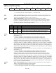
TR2
Bit 2
Timer 2 Run Control. This bit enables/disables the operation of timer 2. Halting this timer
will preserve the current count in TH2, TL2.
0 = Timer 2 is halted.
1 = Timer 2 is enabled.
C/
T2
Bit 1
Counter/Timer Select. This bit determines whether timer 2 will function as a timer or counter.
Independent of this bit, timer 2 runs at 2 clocks per tick when used in either baud rate generator
or clock output mode.
0 = Timer 2 function as a timer. The speed of timer 2 is determined by the T2M bit
(CKCON.5).
1 = Timer 2 will count negative transitions on the T2 pin (P1.0).
CP/
RL2
Bit 0
Capture/Reload Select. This bit determines whether the capture or reload function will be
used for timer 2. If either RCLK or TCLK is set, this bit will not function and the timer will
function in an auto-reload mode following each overflow.
0 = Auto-reloads will occur when timer 2 overflows or a falling edge is detected on T2EX if
EXEN2=1.
1 = Timer 2 captures will occur when a falling edge is detected on T2EX if EXEN2 = 1.
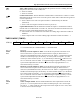
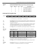
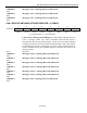
TIMER 2 MODE (T2MOD)
7 6 5 4 3 2 1 0
SFR C9h 1 1 1 D13T1 D13T2 1 T2OE DCEN
R-1 R-1 R-1 RW-0 RW-0 R-1 RW-0 RW-0
R = Unrestricted Read, W = Unrestricted Write, -n = Value after Reset
Bits 7-5 Reserved.
D13T1
Bit 4
Divide-by-13 Clock Option for Timer 1. The D13T1 bit provides an alternate clock
source to the Timer 1 in place of the normal external T1 input pin. When D13T1 is
cleared to 0 (the default Reset state), the clock source for Timer 1 is supplied through the
standard T1 external input pin, the divide-by-12 of the system clock (T1M = 0) or the
divide-by-4 of the oscillator (T1M = 1), as controlled by T1M and C/
T . When D13T1 is
set to a 1 the clock source for Timer 1 is supplied through a separate divide-by-13 of the
system clock independent of T1M. The C/
T bit must also be programmed to a 1 to
select the divide-by-13 counter.
D13T2
Bit 3
Divide-by-13 Clock Option for Timer 2. The D13T2 bit provides an alternate clock
source to the Timer 2 in place of the normal external T2 input pin. When D13T2 is
cleared to 0 (the default Reset state), the clock source for Timer 2 is supplied through the
standard T2 external input pin, the divide-by-12 of the oscillator (T2M = 0) or the divide-
by-4 of the system clock (T2M = 1), as controlled by T2M and C/
2T . When D13T2 is
set to a 1 the clock source for Timer 2 is supplied through a separate divide-by-13 of the
system clock independent of T2M. The C/
2T bit must also be programmed to a 1 to
select the divide-by-13 counter.
Bit 2 Reserved.
T2OE
Bit 1
Timer 2 Output Enable. This bit enables/disables the clock output function of the T2
pin (P1.0). 0 = The T2 pin functions as either a standard port pin or as a counter input
for timer 2. 1 = Timer 2 will drive the T2 pin with a clock output if C/T2=0. Also, timer
2 rollovers will not cause interrupts.