
Users Guide: DS80C390 Supplement Manual


High-Speed Microcontroller User’s Guide: DS80C390 Supplement
58 of 158
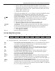
2. Set the CTM bit. At this point the CKRY bit (EXIF.3) will be cleared,
indicating the internal clock stabilization period has commenced. Software is
prohibited from modifying the CD1, CD0 bits while the CKRY bit is cleared.
3. Poll the CKRY bit until it is set.
4. Change CD0, CD1 bits to 00b.
CTM cannot be changed from a 1 to a 0 while the Crystal Clock Multiplier option
is selected by the CD1 and CD0 clock control bits. The CTM is also
automatically cleared to a logic 0 when the processor enters into a Stop mode.
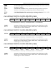
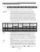
4X/
2X
Bit 3
System Clock Multiplier. This bit selects the internal crystal oscillator
multiplier setting, which in turn establishes a speed of one or two clocks per
machine cycle. This bit can only be altered when the CTM bit is cleared to
prevent the corruption of the system clock.
0 = The device operates at a rate of two clocks per machine cycle.
1 = The device operates at a rate of one clock per machine cycle.
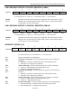
ALEOFF
Bit 2
ALE Disable. This bit disables the expression of the ALE signal on the device
pin during all on-board program and data memory accesses. External memory
accesses will automatically enable ALE independent of the ALEOFF bit.
0 = ALE expression is enabled.
1 = ALE expression is disabled.
Bits 1-0 Reserved. These bits will read 1
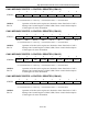
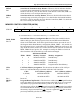
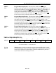
STATUS REGISTER (STATUS)
7 6 5 4 3 2 1 0
SFR C5 PIP HIP LIP — SPTA1 SPRA1 SPTA0 SPRA0
R-0 R-0 R-0 R-* R-0 R-0 R-0 R-0
R = Unrestricted Read, W = Unrestricted Write, -n = Value after Reset, * = See description
PIP
Bit 7
Power-Fail Priority Interrupt Status. When set, this bit indicates that software
is currently servicing a power-fail interrupt. It is cleared when the program
executes the corresponding RETI instruction.
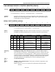
HP
Bit 6
High Priority Interrupt Status. When set, this bit indicates that software is
currently servicing a high priority interrupt. It is cleared when the program
executes the corresponding RETI instruction.
LIP
Bit 5
Low Priority Interrupt Status. When set, this bit indicates that software is
currently servicing a low priority interrupt. It is cleared when the program
executes the corresponding RETI instruction.
Bit 4 Reserved. Read value will be indeterminate.
SPTA1
Bit 3
Serial Port 1 Transmit Activity Monitor. When set, this bit indicates that data
is currently being transmitted by serial port 1. It is cleared when the internal
hardware sets the TI_1 bit. Do not alter the Clock Divide Control bits (PMR.7-6)
while this bit is set or serial port data may be lost.
SPRA1
Bit 2
Serial Port 1 Receive Activity Monitor. When set, this bit indicates that data is
currently being received by serial port 1. It is cleared when the internal hardware
sets the RI_1 bit. Do not alter the Clock Divide Control bits (PMR.7–6) while this
bit is set or serial port data may be lost.