
Users Guide: DS80C390 Supplement Manual


High-Speed Microcontroller User’s Guide: DS80C390 Supplement
43 of 158
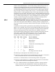
first interrupt source detected by the CAN module following the non-active
interrupt state. The C0IR interrupt values will remain in place until the interrupt
source is removed, independent of other higher (or lower) priority interrupts that
become active prior to clearing the currently displayed interrupt source.
When the current CAN interrupt source is cleared, C0IR will change to
reflect the next active interrupt with the highest priority. The Status Change
interrupt will be asserted if there has been a change in the Can 0 Status
Register (if enabled by the appropriate ERIE and/or STIE bit) and the CAN
Status Interrupt state is set. A message center interrupt will be indicated if the
INTRQ bit in the respective CAN Message Control Register is set.
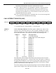
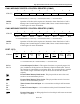
CAN 0 TRANSMIT ERROR REGISTER (C0TE)
7 6 5 4 3 2 1 0
SFR A6h
R*-0 R*-0 R*-0 R*-0 R*-0 R*-0 R*-0 R*-0
R = Unrestricted Read, * = Write only when SWINT = 1 and BUSOFF = 0, -n = Value after Reset
C0TE.7-0
Bits 7-0
CAN 0 Transmit Error Register. This register indicates the number of
accumulated CAN 0 transmit errors. The CAN 0 module responds in different
ways to varying number of errors as shown below.
This register can only be modified by software when SWINT=1 and
BUSOFF=0. All software writes to this register simultaneously load the same
value into the CAN 0 Transmit Error Register and the CAN 0 Receive Error
Register. Writing 00h to this register will also clear the CAN 0 Error Count
Exceeded bit, CECE (C0S.6). This register is cleared following all hardware
Resets and software resets enabled by the CRST bit in the CAN 0 Control
Register.
C0TE Value CAN 0 State
Value < 96 Error active mode, CAN 0 Bus on (BUSOFF=0)
128 > Value ≥ 96
Error active mode, CAN 0 Bus on (BUSOFF=0), warning
level
255 ≥ Value ≥ 128
Error passive mode, CAN 0 Bus on (BUSOFF=0)
Value > 255 CAN 0 Bus off (BUSOFF=1)