
Users Guide: DS80C390 Supplement Manual

High-Speed Microcontroller User’s Guide: DS80C390 Supplement
36 of 158
established by the P4CNT register. Note that the chip-enable range when using
A0-A15 is 32kB instead of the expected 64kB. This is to allow the use of more
common 32kB memory devices rather than 64kB devices.
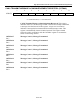
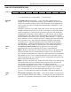
Port 5 Pin Function
P5CNT.2-0 P5.7 P5.6 P5.5 P5.4
000 I/O I/O I/O I/O
100 I/O I/O I/O
PCE0
101 I/O I/O
PCE1 PCE0
110 I/O
PCE2 PCE1 PCE0
111
PCE3 PCE2 PCE1 PCE0
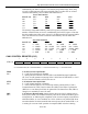
The memory range addressable by each PCEx signal is a function of the total
number of address lines (A19-A16) established by the P4CNT register. Note that
the chip-enable range when using A0-A15 is 32 KB instead of the expected 64kB.
This is to allow the use of more common 32 KB memory devices rather than
64kB devices.
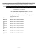
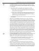
Port 5 Pin Function
P4CNT.5-3
PCE0 PCE1 PCE2 PCE3
000 0 – 32kB 32 – 64kB 64 – 96kB 96 – 128kB
100 0 – 128kB 128 – 256kB 256 – 384kB 384 – 512kB
101 0 – 256kB 256 – 512kB 512 – 768kB 768kB - 1MB
110 0 – 512kB 512 - 1MB 1 - 1.5MB 1.5 - 2MB
111 0 - 1MB 1 - 2M 2 - 3MB 3 - 4MB
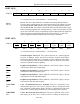
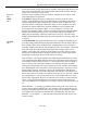
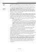
CAN 0 CONTROL REGISTER (C0C)
7 6 5 4 3 2 1 0
SFR A3h ERIE STIE PDE — CRST AUTOB ERCS SWINT
RW-0 RW-0 RW-0 RW-0 RT-1 RW-0 RW-0 RW-1
R = Unrestricted Read, W = Unrestricted Write, T = Timed Access Write Only, -n = Value after Reset
ERIE
Bit 7
CAN 0 Error Interrupt Enable.
0 = CAN 0 Error Interrupt is disabled.
1 = Setting this bit while the C0IE bit (EIE.6) and Global Interrupt Enable bits
(IE.7) are set will generate an interrupt if the CAN 0 Bus Off (BUSOFF) or CAN
0 Error Count Exceeded bit (CECE) bits are set.
STIE
Bit 6
CAN 0 Status Interrupt Enable.
0 = CAN 0 Status Interrupt is disabled.
1 = If the C0IE bit (EIE.6) is set, an interrupt will be generated if the CAN 0
Transmit Status bit (TXS), Receive Status bit (RXS) or the Wake-Up Status bit
(WKS) is set. An interrupt will also be generated if the Status Error bits (ER2-0)
changes to a non-000b or non-111b state.
PDE
Bit 5
CAN 0 Power-Down Enable. Setting this bit places the CAN 0 module into its
lowest power mode. The module will enter power-down mode immediately upon
setting this bit, or following the completion of the current reception, transmission,
arbitration failure, or error condition on CAN 0. Software can poll the PDE bit to
ascertain whether the microcontroller has entered power-down mode (PDE=1) or
is waiting for a current CAN operation to complete (PDE=0) before entering