
Users Guide: DS80C390 Supplement Manual


High-Speed Microcontroller User’s Guide: DS80C390 Supplement
18 of 158
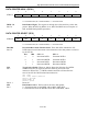
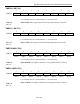
TIMER/COUNTER CONTROL (TCON)
7 6 5 4 3 2 1 0
SFR 88h TF1 TR1 TF0 TR0 IE1 IT1 IE0 IT0
RW-0 RW-0 RW-0 RW-0 RW-0 RW-0 RW-0 RW-0
R = Unrestricted Read, W = Unrestricted Write, -n = Value after Reset
TF1
Bit 7
Timer 1 Overflow Flag. This bit indicates when Timer 1 overflows its
maximum count as defined by the current mode. This bit can be cleared by
software and is automatically cleared when the CPU vectors to the Timer 1
interrupt service routine.
0 = No Timer 1 overflow has been detected.
1 = Timer 1 has overflowed its maximum count.
TR1
Bit 6
Timer 1 Run Control. This bit enables/disables the operation of Timer 1.
0 = Timer 1 is halted.
1 = Timer 1 is enabled.
TF0
Bit 5
Timer 0 Overflow Flag. This bit indicates when Timer 0 overflows its
maximum count as defined by the current mode. This bit can be cleared by
software and is automatically cleared when the CPU vectors to the Timer 0
interrupt service routine or by software.
0 = No Timer 0 overflow has been detected.
1 = Timer 0 has overflowed its maximum count.
TR0
Bit 4
Timer 0 Run Control. This bit enables/disables the operation of Timer 0.
0 = Timer 0 is halted.
1 = Timer 0 is enabled.
IE1
Bit 3
Interrupt 1 Edge Detect. This bit is set when an edge/level of the type defined
by IT1 is detected. If IT1=1, this bit will remain set until cleared in software or
the start of the External Interrupt 1 service routine. If IT1=0, this bit will
inversely reflect the state of the
1INT pin.
IT1
Bit 2
Interrupt 1 Type Select. This bit selects whether the 1INT pin will detect edge
or level triggered interrupts.
0 =
1INT is level triggered.
1 =
1INT is edge triggered.
IE0
Bit 1
Interrupt 0 Edge Detect. This bit is set when an edge/level of the type defined
by IT0 is detected. If IT0=1, this bit will remain set until cleared in software or
the start of the External Interrupt 0 service routine. If IT0=0, this bit will
inversely reflect the state of the
0INT pin.
IT0
Bit 0
Interrupt 0 Type Select. This bit selects whether the 0INT pin will detect edge
or level triggered interrupts.
0 =
0INT is level triggered.
1 =
0INT is edge triggered.