
Users Guide: DS80C390 Supplement Manual


High-Speed Microcontroller User’s Guide: DS80C390 Supplement
17 of 158
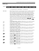
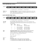
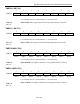
POWER CONTROL (PCON)
7 6 5 4 3 2 1 0
SFR 87h SMOD_0 SMOD0 OFDF ODFE FG1 FG0 STOP IDLE
RW-0 RW-0 RW-0* RW-0 RW-0 RW-0 RW-0 RW-0
R = Unrestricted Read, W = Unrestricted Write, -n = Value after Reset, * = See description
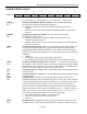
SMOD_0
Bit 7
Serial Port 0 Baud Rate Doubler Enable. This bit enables/disables the
serial baud rate doubling function for Serial Port 0.
0 = Serial Port 0 baud rate will be that defined by baud rate generation
equation.
1 = Serial Port 0 baud rate will be double that defined by baud rate generation
equation.
SMOD0
Bit 6
Framing Error Detection Enable. This bit selects function of the
SCON0.7 and SCON1.7 bits.
0 = SCON0.7 and SCON1.7 control the SM0 function defined for the
SCON0 and SCON1 registers.
1 = SCON0.7 and SCON1.7 are converted to the Framing Error (FE) flag for the
respective Serial Port.
OFDF
Bit 5
Oscillator Fail Detect Flag. When set, this bit indicates that the preceding reset
was caused by the detection of the crystal oscillator frequency falling below
approximately 30kHz while the OFDE bit was set. This bit must be cleared by
software. This bit not altered (and no reset will be generated) under the following
conditions:
1. OFDE = 0
2. An oscillator halt associated with entering Stop mode.
3. An oscillator halt associated with running from the internal ring oscillator.
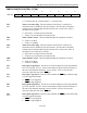
OFDE
Bit 4
Oscillator-Fail Detect Enable. When the OFDE = 1, a system reset is generated
any time the crystal oscillator frequency falls below approximately 30kHz. When
the OFDE bit is cleared to logic 0, no reset is issued when the crystal falls below
30kHz. The OFDE is cleared to logic 0 by any reset source.
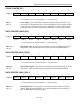
GF1
Bit 3
General-Purpose User Flag 1. This is a bit-addressable, general-purpose flag for
software control.
GF0
Bit 2
General-Purpose User Flag 0. This is a bit-addressable, general-purpose flag for
software control.
STOP
Bit 1
Stop Mode Select. Setting this bit stops program execution, halts the CPU
oscillator and internal timers, and places the CPU in a low-power mode. This bit
is cleared and operation resumed by an external reset, or execution of an enabled
external interrupt. This bit is always read as 0. Setting this bit while IDLE = 1
places the device in an undefined state. Setting this bit also clears the CTM bit.
This bit cannot be set while eithe rCAN module is active, i.e., SWINT = CRST =
PDE = 0, or if there is any CAN bus activity while C0_I/O = 1, or C1_I/O = 1.
The following sequence should be used to activate Stop mode.
1. Set (CRST or SWINT or PDE) = 1 for both CANs,
2. Clear all CAN bus activity bits for both CANs,
3. Set Stop = 1.
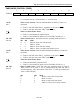
IDLE
Bit 0
Idle Mode Select. Setting this bit stops program execution but leaves the CPU
oscillator, timers, serial ports, and interrupts active. This bit is always reads as 0.