
Users Guide: DS80C390 Supplement Manual


High-Speed Microcontroller User’s Guide: DS80C390 Supplement
15 of 158
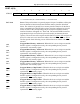
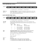
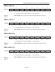
STACK POINTER (SP)
7 6 5 4 3 2 1 0
SFR 81h SP.7 SP.6 SP.5 SP.4 SP.3 SP.2 SP.1 SP.0
RW-0 RW-0 RW-0 RW-0 RW-0 RW-1 RW-1 RW-1
R = Unrestricted Read, W = Unrestricted Write, -n = Value after Reset
SP.7-0
Bits 7-0
Stack Pointer. This stack pointer identifies current location of the stack. The
stack pointer is incremented before every PUSH operation. This register defaults
to 07h after reset. When the 10-bit stack is enabled (SA=1), this register will be
combined with the extended stack pointer (ESP;9Bh) to form the 10-bit address.
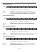
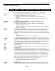
DATA POINTER LOW 0 (DPL)
7 6 5 4 3 2 1 0
SFR 82h DPL.7 DPL.6 DPL.5 DPL.4 DPL.3 DPL.2 DPL.1 DPL.0
RW-0 RW-0 RW-0 RW-0 RW-0 RW-0 RW-0 RW-0
R = Unrestricted Read, W = Unrestricted Write, -n = Value after Reset
DPL.7-0
Bits 7-0
Data Pointer Low 0. This register is the low byte of the standard 80C32 16-bit
data pointer. DPL and DPH are used to point to non-scratchpad data RAM.
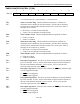
DATA POINTER HIGH 0 (DPH)
7 6 5 4 3 2 1 0
SFR 83h DPH.7 DPH.6 DPH.5 DPH.4 DPH.3 DPH.2 DPH.1 DPH.0
RW-0 RW-0 RW-0 RW-0 RW-0 RW-0 RW-0 RW-0
R = Unrestricted Read, W = Unrestricted Write, -n = Value after Reset
DPH.7-0
Bits 7-0
Data Pointer High 0. This register is the high byte of the standard 80C32 16-bit
data pointer. DPL and DPH are used to point to non-scratchpad data RAM.
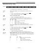
DATA POINTER LOW 1 (DPL1)
7 6 5 4 3 2 1 0
SFR 84h DPL1.7 DPL1.6 DPL1.5 DPL1.4 DPL1.3 DPL1.2 DPL1.1 DPL1.0
RW-0 RW-0 RW-0 RW-0 RW-0 RW-0 RW-0 RW-0
R = Unrestricted Read, W =Unrestricted Write, -n = Value after Reset
DPL1.7-0
Bits 7-0
Data Pointer Low 1. This register is the low byte of the auxiliary 16-bit data
pointer. When the SEL bit (DPS.0) is set, DPL1 and DPH1 are used in place of
DPL and DPH during DPTR operations.