
Manual

High-Speed Microcontroller User’s Guide
Rev: 062210 85 of 176
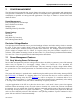
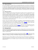
varied, allowing fast RAM’s but slow peripherals. The first stretch allows the use of common 120ns or
150ns RAMs without dramatically lengthening the memory access. Note that the first Stretch value does
not follow the pattern of adding four clocks to the strobe. This is because the first Stretch uses one clock
to create additional setup and one clock to create additional hold time. Systems using a Stretch cycle of
zero are presumed to be fast enough or to be running at a slower clock speed. Since the Stretch is based
on crystal timing, the resulting pulse widths must be viewed on the basis of the real system timing.
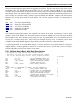
Table 6-C. Data Memory Cycle Stretch Values
CKCON.2–0
RD OR WR STROBE WIDTH
M2 M1 M0
MEMORY CYCLES
IN CLOCK t at 25MHz (ns) t at 12MHz (ns)
0 0 0 2 2 80 167
0 0 1 3 (default) 4 160 333
0 1 0 4 8 320 667
0 1 1 5 12 480 1000
1 0 0 6 16 640 1333
1 0 1 7 20 800 1667
1 1 0 8 24 960 2000
1 1 1 9 28 1120 2333
Note: These numbers represent nominal values. Actual timing may vary slightly.
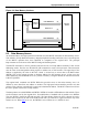
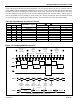
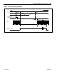
Figure 6-4. Full-Speed MOVX Instruction
ALE
PSEN
CLK
C1 C2 C3 C4 C1 C2 C3 C4 C1
C2
C3 C4 C1 C2 C3 C4
Last Cycle of
Previous
Instruction
First
Machine
C
y
cle
Second
Machine
C
y
cle
MOVX Instruction
WR
Next
Instruction
Machine
Cycle
PORT 0
PORT 2
A0
-
A7
D0
-
D7
A0
-
A7
D0
-
D7
A0
-
A7
D0
-
D7
A0
-
A7
A0
-
A7
MOVX
Instruction
Address
Next
Instruction
Address
MOVX
Instruction
Next
Instruction
Read
MOVX
Data
Addres
s
MOVX
Data
A8-A15
A
8-
A
15
A
8-
A
15 A8-A15
DATA MEMORY WRITE (2-CYCLE, STRETCH = 0)