
Manual

High-Speed Microcontroller User’s Guide
Rev: 062210 53 of 176
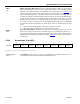
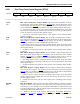
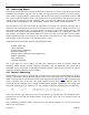
4.2.47 Real-Time Alarm Second Register (RTAS)
7 6 5 4 3 2 1 0
SFR F3h 0 0
RTAS.5
RTAS.4 RTAS.3
RTAS.2
RTAS.1 RTAS.0
RW-0 RW-0 RW-* RW-* RW-*
RW-*
RW-* RW-*
R = Unrestricted Read, W = Unrestricted Write, -n = Value after Reset, * = See description
Bits 7, 6 Reserved. These bits will be 0 when read.
RTAS.5–RTAS.0
Bits 5–0
Real-Time Alarm Second. These bits represent the second alarm that will be compared
against the RTC Second register (RTCS
;FBh). The ability of a match between the two
registers to cause an alarm is controlled by the RTC Second Register Compare Enable
bit (RTCC
.6). This register should only be loaded with values from 0 to 3Bh (0 to 59
seconds). The contents of this register will be indeterminate following a no-battery reset
(except bits 7, 6), and unchanged by all other forms of reset.
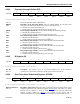
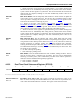
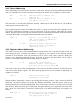
4.2.48 Real-Time Alarm Minute Register (RTAM)
7 6 5 4 3 2 1 0
SFR F4h 0 0
RTAM.5
RTAM.4 RTAM.3
RTAM.2
RTAM.1 RTAM.0
R-0 R-0 RW-* RW-* RW-*
RW-*
RW-* RW-*
R = Unrestricted Read, W = Unrestricted Write, -n = Value after Reset, * = See Description
Bits 7, 6 Reserved. These bits will be 0 when read.
RTAM.5–RTAM.0
Bits 5–0
Real-Time Alarm Minute. These bits represent the minute alarm that will be compared
against the RTC Minute register (RTCM
;FCh). The ability of a match between the two
registers to cause an alarm is controlled by the RTC Minute Register Compare Enable
bit (RTCC
.5). This register should only be loaded with values from 0 to 3Bh (0 to 59
minutes). The contents of this register will be indeterminate following a no-battery reset
(except bits 7, 6), and unchanged by all other forms of reset.
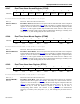
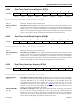
4.2.49 Real-Time Alarm Hour Register (RTAH)
7 6 5 4 3 2 1 0
SFR F5h 0 0
0 RTAH.4
RTAH.3
RTAH.2
RTAH.1 RTAH.0
R-0 R-0 R-0
RW-*
RW-*
RW-*
RW-* RW-*
R = Unrestricted Read, W = Unrestricted Write, -n = Value after Reset, * = See Description
Bits 7, 6, 5 Reserved. These bits will be 0 when read.
RTAH.4–RTAH.0
Bits 4–0
Real-Time Alarm Hour. These bits represent the hour alarm which will be compared
against the RTC Hour register (RTCH
;FDh). The ability of a match between the two
registers to cause an alarm is controlled by the RTC Hour Register Compare Enable bit
(RTCC
.4). This register should only be loaded with values from 0 to 17h (0 to 23
hours). The day of week bits DOW2-0, located in RTCH
.7-5 do not have a
corresponding alarm feature. The contents of this register will be indeterminate
following a no-battery reset (except bits 7, 6, 5), and unchanged by all other forms of
reset.