
Manual

High-Speed Microcontroller User’s Guide
Rev: 062210 46 of 176
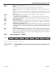
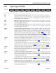
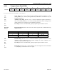
4.2.34 Timed Access Register (TA)
7 6 5 4 3 2 1 0
SFR C7h TA.7 TA.6
TA.5
TA.4 TA.3
TA.2
TA.1 TA.0
W-1 W-1 W-1 W-1 W-1
W-1
W-1 W-1
W = Unrestricted Write, -n = Value after Reset
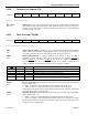
TA.7–TA.0
Bits 7–0
Timed Access. Correctly accessing this register permits modification of timed-access
protected bits. Write AAh to this register first, followed within 3 cycles by writing 55h.
Timed-access protected bits can then be modified for a period of 3 cycles measured
from the writing of the 55h.
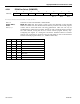
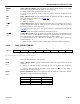
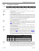
4.2.35 Timer 2 Control (T2CON)
7 6 5 4 3 2 1 0
SFR C8h TF2 EXF2
RCLK
TCLK EXEN2
TR2
C/
T2 CP/RL2
RW-0 RW-0 RW-0 RW-0 RW-0
RW-0
RW-0 RW-0
R = Unrestricted Read, W = Unrestricted Write, -n = Value after Reset
TF2
Bit 7
Timer 2 Overflow Flag. This flag will be set when Timer 2 overflows from FFFFh to
0000h, or the count equal to the capture register in down count mode. It must be cleared
by software. TF2 will only be set if RCLK and TCLK are both cleared to 0.
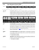
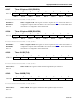
EXF2
Bit 6
Timer 2 External Flag. A negative transition on the T2EX pin (P1.1) or timer 2
underflow/overflow will cause this flag to set based on the CP/
RL2 (T2CON.0),
EXEN2 (T2CON
.3), and DCEN (T2MOD.0) bits. If set by a negative transition, this
flag must be cleared to 0 by software. Setting this bit in software or detection of a
negative transition on the T2EX pin will force a timer interrupt if enabled.
CP/RL2 EXEN2 DCEN RESULT
1 0 X Negative transitions on P1.1 will not affect this bit.
1 1 X Negative transitions on P1.1 will set this bit.
0 0 0 Negative transitions on P1.1 will not affect this bit.
0 1 0 Negative transitions on P1.1 will set this bit.
0 X 1
Bit toggles whenever timer 2 underflows/overflows and can be used as a 17th
bit of resolution. In this mode, EXF2 will not cause an interrupt.
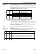
RCLK
Bit 5
Receive Clock Flag. This bit determines the serial port 0 time base when receiving data
in serial modes 1 or 3.
0 = Timer 1 overflow is used to determine receiver baud rate for serial port 0.
1 = Timer 2 overflow is used to determine receiver baud rate for serial port 0.
Setting this bit will force timer 2 into baud-rate generation mode. The timer will operate
from a divide-by-2 of the external clock.
TCLK
Bit 4
Transmit Clock Flag. This bit determines the serial port 0 time base when transmitting
data in serial modes 1 or 3.
0 = Timer 1 overflow is used to determine transmitter baud rate for serial port 0.
1 = Timer 2 overflow is used to determine transmitter baud rate for serial port 0. Setting
this bit will force timer 2 into baud-rate generation mode. The timer will operate from a
divide-by-2 of the external clock.