
Manual


High-Speed Microcontroller User’s Guide
Rev: 062210 27 of 176
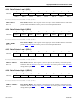
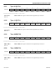
4.2.7 Data Pointer Select (DPS)
7 6 5 4 3 2 1 0
SFR 86h 0 0
0
0 0 0 0 SEL
R-0 R-0 R-0 R-0 R-0 R-0 R-0 RW-0
R = Unrestricted Read, W = Unrestricted Write, -n = Value after Reset
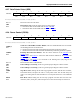
Bits 7-1
Reserved. These bits will read 0.
SEL
Bit 0
Data Pointer Select. This bit selects the active data pointer.
0 = Instructions that use the DPTR will use DPL
and DPH.
1 = Instructions that use the DPTR will use DPL1
and DPH1.
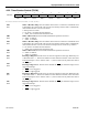
4.2.8 Power Control (PCON)
7 6 5 4 3 2 1 0
SFR 87h SMOD_0 SMOD0
—
— GF1 GF0 STOP IDLE
RW-0 RW-0 RW-0 RW-0 RW-0 RW-0
R = Unrestricted Read, W = Unrestricted Write, -n = Value after Reset
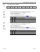
SMOD_0
Bit 7
Serial Port 0 Baud-Rate Doubler Enable. This bit enables/disables the serial baud-
rate doubling function for Serial Port 0.
0 = Serial Port 0 baud rate will be that defined by baud-rate generation equation.
1 = Serial Port 0 baud rate will be double that defined by baud-rate generation equation.
SMOD0
Bit 6
Framing Error-Detection Enable. This bit selects function of the SCON0
.7 and
SCON1
.7 bits.
0 = SCON0
.7 and SCON1.7 control the SM0 function defined for the SCON0 and
SCON1
registers.
1 = SCON0
.7 and SCON1.7 are converted to the Framing Error (FE) flag for the
respective Serial Port.
Bits 5-4 Reserved. Read data is indeterminate.
GF1
Bit 3
General-Purpose User Flag 1. This is a general-purpose flag for software control.
GF0
Bit 2
General-Purpose User Flag 0. This is a general-purpose flag for software control.
STOP
Bit 1
Stop Mode Select. Setting this bit will stop program execution, halt the CPU oscillator,
and internal timers, and place the CPU in a low-power mode. This bit will always be
read as a 0. Setting this bit while the Idle bit is set will place the device in an undefined
state.
IDLE
Bit 0
Idle Mode Select. Setting this bit will stop program execution but leave the CPU
oscillator, timers, serial ports, and interrupts active. This bit will always be read as a 0.