
Manual


High-Speed Microcontroller User’s Guide
Rev: 062210 25 of 176
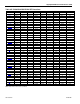
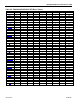
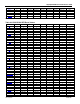
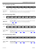
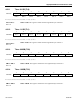
REGISTER BIT 7 BIT 6 BIT 5 BIT 4 BIT 3 BIT 2 BIT 1 BIT 0 ADDRESS
B 0 0 0 0 0 0 0 0 F0h
RTASS SPECIAL SPECIAL SPECIAL SPECIAL SPECIAL SPECIAL SPECIAL SPECIAL F 2h
RTAS 0 0 SPECIAL SPECIAL SPECIAL SPECIAL SPECIAL SPECIAL F 3 h
RTAM 0 0 SPECIAL SPECIAL SPECIAL SPECIAL SPECIAL SPECIAL F 4 h
RTAH 0 0 0 SPECIAL SPECIAL SPECIAL SPECIAL SPECIAL F 5 h
EIP — — 0 0 0 0 0 0 F8h
RTCC SPECIAL SPECIAL SPECIAL SPECIAL 0 0 SPECIAL SPECIAL F 9 h
RTCSS SPECIAL SPECIAL SPECIAL SPECIAL SPECIAL SPECIAL SPECIAL SPECIAL F Ah
RTCS 0 0 SPECIAL SPECIAL SPECIAL SPECIAL SPECIAL SPECIAL F B h
RTCM 0 0 SPECIAL SPECIAL SPECIAL SPECIAL SPECIAL SPECIAL FC h
RTCH SPECIAL SPECIAL SPECIAL SPECIAL SPECIAL SPECIAL SPECIAL SPECIAL F Dh
RTCD0 SPECIAL SPECIAL SPECIAL SPECIAL SPECIAL SPECIAL SPECIAL SPECIAL FE h
RTCD1 SPECIAL SPECIAL SPECIAL SPECIAL SPECIAL SPECIAL SPECIAL SPECIAL F F h
Most of the unique features of the high-speed microcontroller family are controlled by bits in SFRs
located in unused locations in the 8051 SFR map. This allows for increased functionality while
maintaining complete instruction set compatibility.
The descriptions for each bit indicates its read and write access as well as its state after a power-on reset.
Bits that are affected by a no-battery reset are also indicated. Note that many bits and registers are unique
to specific devices, and their functions will vary between different members of the high-speed
microcontroller family.
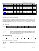
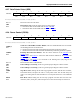
4.2.1 Port 0 (P0)
7 6 5 4 3 2 1 0
SFR 80h P0.7 P0.6
P0.5
P0.4 P0.3 P0.2 P0.1 P0.0
RW-1 RW-1 RW-1 RW-1 RW-1 RW-1 RW-1 RW-1
R = Unrestricted Read, W = Unrestricted Write, -n = Value after Reset
P0.7–P0.0
Bits 7–0
Port 0. This port functions as a multiplexed address/data bus during external memory
access, and as a generalpurpose I/O port on devices which incorporate internal program
memory. During external memory cycles, this port will contain the LSB of the address
when ALE is high, and data when ALE is low.
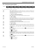
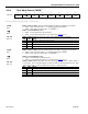
4.2.2 Stack Pointer (SP)
7 6 5 4 3 2 1 0
SFR 81h SP.7 SP.6
SP.5
SP.4 SP.3 SP.2 SP.1 SP.0
RW-0 RW-0 RW-0 RW-0 RW-0 RW-1 RW-1 RW-1
R = Unrestricted Read, W = Unrestricted Write, -n = Value after Reset
SP.7—SP.0
Bits 7–0
Stack Pointer. This stack pointer identifies the location where the stack will begin. The
stack pointer is incremented before every PUSH operation. This register defaults to 07h
after reset.