
Manual


High-Speed Microcontroller User’s Guide
Rev: 062210 136 of 176
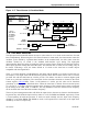
12. SERIAL I/O
The high-speed microcontroller serial communication is compatible with the 80C32. This includes
framing error detection and automatic address recognition. The high-speed microcontroller provides two
fully independent UARTs (serial ports) for simultaneous communication over two channels. The UARTs
can be operated in identical or different modes and communication speeds. In this documentation, all
descriptions apply to both UARTs unless stated otherwise.
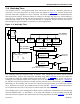
Each serial port is capable of both synchronous and asynchronous modes. In the synchronous mode, the
microcontroller generates the clock and operates in a half-duplex mode. In the asynchronous mode, full
duplex operation is available. Receive data is buffered in a holding register. This allows the UART to
receive an incoming word before software has read the previous value. Each UART has an associated
control register (SCON0
, SCON1) and each has a transmit/receive register (SBUF0, SBUF1). The SFR
locations are: SCON0
;98h; SBUF0; 99h; SCON1;C0h; SBUF1;C1h. The SBUF location provides access
to both transmit and receive registers. Reads are directed to the receive buffer and writes to the transmit
buffer automatically.
12.1 Serial Mode Summary
Each port provides four operating modes. These offer different communication protocols and baud rates.
These modes are summarized briefly as follows. Detailed descriptions are provided later in this section.
The use of power management modes, if supported, will affect the internal clock rate and baud rate as
shown in Table 7-D
. The following descriptions assume that power management modes are not in use.
12.1.1 Mode 0
This mode provides synchronous communication with external devices. It is commonly used to
communicate with serial peripherals. Serial I/O occurs on the RXD pin. The shift clock is provided on the
TXD pin. Note that whether transmitting or receiving, the high-speed microcontroller generates the serial
clock. Thus, any device on the serial port in Mode 0 must accept the microcontroller as the master.
The baud rate in Mode 0 is a function of the oscillator input. It will be the clock input divided by either 12
or 4. This is selected by the SM2 bit (SCON0
.5 or SCON1.5) as described below. When set to a logic 0,
the serial port runs at a divide-by-12. When set to a logic 1, the serial port runs at a divide-by-4. With the
exception of the additional new divide-by-4 of the oscillator (supported by SM2), Mode 0 operation is
identical to the 80C32.
12.1.2 Mode 1
This mode provides standard full-duplex asynchronous communication. A total of 10 bits is transmitted
including 1 start bit, 8 data bits, and 1 stop bit. The received stop bit is stored in bit location RB8 in the
relevant SCON register.
In Mode 1, the baud rate is a function of timer overflow. This makes the baud rate programmable by the
user. Mode 1 has a difference for the two UARTs. Serial Port 0 can use either Timer 1 or 2 to generate
baud rates. Serial Port 1 can use only Timer 1. Note that if both serial ports use the same timer, they will
be running at the same baud rate. If they use different timers (or different modes), they can run at
different rates. Baud rates are discussed in more detail below. Mode 1 operation is identical to the
standard 80C32 when Timers 1 or 2 use the default divide-by-12 of the oscillator.