
Manual


High-Speed Microcontroller User’s Guide
Rev: 062210 135 of 176
11.9.2 Clock Control Register (CKCON) Summary
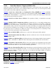
CKCON.7: Watchdog Timer Mode Select Bit 1 (WD1). See table below for operation.
CKCON.6: Watchdog Timer Mode Select Bit 0 (WD0). See table below for operation. The WD select
bits determine the timeout period of the watchdog timer. The timer divides the crystal frequency by a
programmable value as shown below. The divider value is expressed in number of clock (crystal) cycles.
Note that the reset timeout is 512 clocks longer than the interrupt, regardless of whether the interrupt is
enabled.
WD1 WD0 Interrupt Divider Reset Divider
0 0 2
17
2
17
+ 512
0 1 2
20
2
20
+ 512
1 0 2
23
2
23
+ 512
1 1 2
26
2
26
+ 512
The default watchdog timeout is the shortest one (WD1 = WD0 = 0). Software can change this value
easily, so this should cause no inconvenience. However, the EWT, WDIF, and RWT bits are protected
under the timed-access procedure. This prevents software from accidentally enabling or disabling the
watchdog. Most importantly, it prevents errant code from accidentally clearing and restarting the
watchdog. More details are discussed in the section on timed access.