
Manual


High-Speed Microcontroller User’s Guide
Rev: 062210 134 of 176
by-64 or divide-by-1024 is used as the input source for the watchdog timer. This allows the watchdog
period to remain synchronized with device operation.
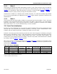
As discussed, the watchdog timer has several SFR bits that contribute to its operation. It can be enabled to
function as either a reset source, interrupt source, software polled timer or any combination of the three.
Both the reset and interrupt have status flags. The watchdog also has a bit that restarts the timer. A
summary table showing the bit locations is below. A description follows.
NAME DESCRIPTION REGISTER LOCATION BIT POSITION
EWT Enable Watchdog Timer Reset WDCON–D8h WDCON.1
RWT Reset Watchdog Timer WDCON–D8h WDCON.0
WD1 Watchdog Interval 1 CKCON–8Eh CKCON.7
WD0 Watchdog Interval 0 CKCON–8Eh CKCON.6
WTRF Watchdog Timer Reset Flag WDCON–D8h WDCON.2
EWDI Enable Watchdog Timer Interrupt EIE–E8h EIE.4
WDIF Watchdog Interrupt Flag WDCON–D8h WDCON.3
The watchdog timer is a free-running timer and will be disabled by a power-fail reset. A watchdog
timeout reset will not disable the watchdog timer but will restart the timer. In general, software should set
the watchdog to whichever state is desired, just to be certain of its state. Control bits that support
watchdog operation are described below.
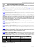
11.9.1 Watchdog Control Register (WDCON) Summary
WDCON.3: Watchdog Interrupt Flag (WDIF). If the watchdog interrupt is enabled (EIE.4), hardware
will set this bit to indicate that the watchdog interrupt has occurred. If the interrupt is not enabled, this bit
indicates that the timeout has passed. If the watchdog reset is enabled (WDCON
.1), the user has 512
clocks to strobe the watchdog prior to a reset. Software or any reset can clear this flag.
WDCON.2: Watchdog Timer Reset Flag (WTRF). Hardware will set this bit when the watchdog timer
causes a reset. Software can read it, but must clear it manually. A power-fail reset will also clear the bit.
This bit assists software in determining the cause of a reset. If EWT = 0, the watchdog timer will have no
effect on this bit.
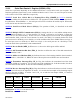
WDCON.1: Enable Watchdog Timer Reset (EWT). Setting this bit will turn on the watchdog timer
reset function. The interrupt will not occur unless the EWDI bit in the EIE
register is set. A reset will
occur according to the WD1 and WD0 bits in the CKCON
register. Setting this bit to a 0 will disable the
reset but leave the timer running.
WDCON.0: Reset Watchdog Timer (RWT). This bit serves as the strobe for the watchdog function.
During the timeout period, software must set the RWT bit if the watchdog is enabled. Failing to set the
RWT will cause a reset when the timeout has elapsed. There is no need to set the RWT bit to a 0 because
it is self-clearing.
Read/Write Access: All bits have unrestricted read access. POR, EWT, WDIF, and RWT require a
timed-access write. The remaining bits have unrestricted write access.