
Manual


High-Speed Microcontroller User’s Guide
Rev: 062210 130 of 176
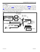
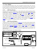
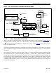
Figure 11-6. Timer/Counter 2, Baud-Rate Generator Mode
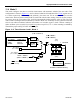
11.7.6 Timer Output Clock Generator
Timer 2 can also be configured to drive a clock output on port pin P1.0 (T2) as shown in Figure 11-7. To
configure Timer 2 for this mode, first it must be set to 16-bit auto-reload timer mode (CP/
RL2 = 0,
C/
T2
= 0). Next, the T2OE (T2MOD.1) bit must be set to a logic 1. TR2 (T2CON.2) must also be set to a
logic 1 to enable the timer.
This mode will produce a 50% duty cycle square-wave output. The frequency of the square wave is given
by the formula in the figure. Each timer overflow causes an edge transition on the pin, i.e., the state of the
pin toggles.
Note that this mode has two somewhat unique features in common with the baud-rate generation mode.
First, the time base is the crystal frequency divided by 2, and no other divider selection is possible.
Second, the timer itself will not generate an interrupt, but if needed, an additional external interrupt may
be caused using T2EX as described above. Because of the two mode’s similarities, the timer can be used
to generate both an external clock and a baud-rate clock simultaneously. Once the clock-out mode is
established, either TCLK or RCLK is set to 1, and the RCAP2 registers are loaded, the timer will provide
a clock to both functions.
OSC INPUT TO TIMER
CLK MODE TIMER INPUT
DIVIDE-BY-4 OSC/2
PMM1 OSC/82
PMM2 OSC/512
DIVIDE
BY 2
T2 = P1.0
TR2 = T2CON.2
EXEN2 = T2CON.3
EXF2 =
T2
CO
N.
6
TIMER 2
INTERRUPT
0
1
TL2
0
7
TH2
8
15
RCLK =
T2
CO
N.
5
0
7
8
15
RCAP2L
RCAP2H
T2EX = P1.1
Tx
CLOCK
DIVIDE
BY 1
6
Rx
CLOCK
DIVIDE
BY 1
6
SMOD =
WDCON.7
TCLK =
T2
CO
N.4
1
0
1
0
0
1
TIMER 1
O
VERFL
O
W
C/
T2
= T2COD.1
CLK