
Manual


High-Speed Microcontroller User’s Guide
Rev: 062210 126 of 176
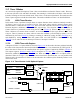
11.7 Timer 2 Modes
As is seen in the register descriptions, Timer 2 has several abilities not found in Timers 0 and 1. However,
it does not offer the 13-bit and dual 8-bit modes, thus running in 16-bit mode at all times. Also note that
instead of offering an 8-bit auto-reload mode, Timer 2 has a 16-bit auto-reload mode. This mode uses the
Timer Capture registers to hold the reload values. The modes available on Timer 2 are described below.
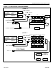
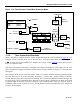
11.7.1 16-Bit Timer/Counter
In this mode, Timer 2 performs a simple timer or counter function where it behaves similarly to mode 1
of Timers 0 and 1, but uses 16 instead of 8 bits. This mode, along with the optional capture mode
described below, is illustrated in Figure 11-4
. The 16-bit count values are found in TL2 and TH2 Special
Function Registers (addresses 0CCh and 0CDh, respectively). The selection of whether a Timer or
Counter function is performed is made using the bit C/
T2
(T2CON.1). When C/
T2
is set to a logic 1,
Timer 2 behaves as a counter where it counts 1-to-0 transitions at the T2 (P1.0) pin. When C/
T2 is set to
a logic 0, Timer 2 functions as a timer where it counts the oscillator cycles divided by either 12 or 4 as
determined by bit T2M (T2CON
.5). Timing or counting is enabled by setting bit TR2 (T2CON.2) to 1,
and disabled by setting it to 0. When the counter rolls over from FFFFh to 0000h, the TF2 flag
(T2CON
.7) is set and will cause an interrupt if Timer 2’s interrupt is enabled.
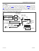
11.7.2 16-Bit Timer with Capture
A diagram of Timer 2’s Capture Mode is shown in Figure 11-4. In this mode, the timer performs basically
the same 16-bit timer/counter function described above. However, a 1-to-0 transition on T2EX (pin P1.1)
causes the value in Timer 2 to be transferred into the capture registers if enabled by EXEN2 (T2CON
.3).
The capture registers, RCAP2L
and RCAP2H, correspond to TL2 and TH2, respectively. The capture
function is enabled by the CP/
RL2 (T2CON.0) bit. When set to logic 1, the timer is in capture mode as
described. When set to logic 0, the timer is in auto-reload mode described later. As was possible with
Timers 0 and 1, the time base for Timer 2 can be selected to be oscillator cycles divided by either 12 or 4
when in this mode.
Figure 11-4. Timer/Counter 2 with Optional Capture
C/
T2
= T2CON.1
CLK
OSC INPUT TO TIMER
CLK MODE TIMER INPUT
DIVIDE-BY-4 OSC/1
PMM1 OSC/16
PMM2 OSC/256
DIVIDE
BY 12
DIVIDE
BY 4
T2 = P1.0
TR2 = T2CON.2
EXEN2 = T2CON.3
EXF2 =
T2CON.6
CAPTURE
TIMER 2
INTERRUPT
0
1
0
1
T2M = CKCON.5
TL2
0
7
TH2
8
15
TF2 =
T2CON.7
0
7
8
15
RCAP2L
RCAP2H
T2EX = P1.1