
Manual


High-Speed Microcontroller User’s Guide
Rev: 062210 123 of 176
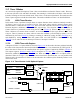
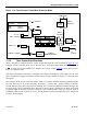
11.5 Mode 3
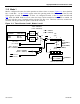
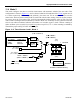
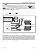
This mode provides an 8-bit timer/counter and a second 8-bit timer as indicated in Figure 11-3. In Mode
3, TL0 is an 8-bit timer/counter controlled by the normal Timer 0 bits (TR0 = TCON
.4 and TF0 =
TCON
.5). TL0 can be used to count oscillator cycles (crystal/12 or crystal/4) or 1-to-0 transitions on pin
T0 as determined by C/
T (TMOD.2). As in the other modes, the GATE function can use INT0 to give
external run control of the timer to an outside signal.
TH0 becomes an independent 8-bit Timer in Mode 3, however it can only count oscillator cycles (divided
by 12 or 4) as shown in the figure. In this mode, some of Timer 1’s control signals are used to manipulate
TH0. That is, TR1 (TCON
.6) and TF1 (TCON.7) become the relevant control and flag bits associated
with TH0.
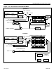
Figure 11-3. Timer/Counter 0 Mode 3
In Mode 3, Timer 1 stops counting and holds its value. Thus, Timer 1 has no practical application while
in Mode 3.
As mentioned above, when Timer 0 is in Mode 3, it uses some of Timer 1’s resources (i.e., TR1 and
TF1). Timer 1 can still be used in Modes 0, 1, and 2 in this situation, but its flexibility becomes somewhat
limited. While it maintains its basic functionality, its inputs and outputs are no longer available. Therefore
when Timer 0 is in Mode 3, Timer 1 can only count oscillator cycles, and it does not have an interrupt or
flag. With these limitations, baud-rate generation is its most practical application, but other time-base
functions may be achieved by reading
the registers.
OSC INPUT TO TIMER
CLK MODE TIMER INPUT
DIVIDE-BY-4 OSC/1
PMM1 OSC/16
PMM2 OSC/256
DIVIDE
BY 12
DIVIDE
BY 4
T0 = P3.4
TR0 = TCON.4
GATE = TMOD.3
TL0
0
7
0
7
TH
0
0
1
0
1
T0M = CKCON.3
TR1 = TCON.6
TF0 = TCON.5
INTERRUPT
TF1 = TCON.7
C/ T = TMOD.2
INT0 = P3.2
CLK
INTERRUPT