
Manual


High-Speed Microcontroller User’s Guide
Rev: 062210 121 of 176
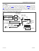
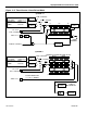
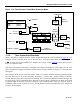
11.3 Mode 1
Mode 1 configures the timer for 16-bit operation as either a timer or counter. Figure 11-1 shows that bits
M1 = 0 and M0 = 1 of the TMOD
register select this operating mode. For Timer n, all of the TLn and
THn registers are used. For example, if Timer 1 is configured in mode 1, then TL1
holds the LSB and
TH1
holds the MSB. Rollover occurs when the timer reaches transitions from FFFFh to 0000h. An
interrupt will also occur if enabled and the relevant TFn flag is set. Time-base selection, counter/timer
selection, and the gate function operate as described in mode 0.
Figure 11-1. Timer/Counter 0 and 1, Modes 0 and 1
MODE 0
M1, M0=TMOD.1,
TMOD.0
(M1, M0=TMOD.5,
TMOD.4
)
OSC INPUT TO TIMER
CLK MODE TIMER INPUT
DIVIDE-BY-4 OSC/1
PMM1 OSC/16
PMM2 OSC/256
DIVIDE
BY 12
DIVIDE
BY 4
T0 = P3.4
(
T1 = P3.5
)
TR0 = TCON.4
(TR1 = TCON.6)
GATE = TMOD.3
(GATE = TMOD.7)
INT0 = P3.2
(
INT1
= P3.3)
TF0 = TCON.5
(
TF1 = T
CO
N.7
)
TIMER 1 FUNCTIONS
SHOWN IN PARENTHESIS
()
INTERRUPT
TL0
(TL1)
0
4
7
00
01
0
7
TH0
(
TH1
)
CLK
0
1
0
1
T0M = CKCON.3
(T1M = CKCON.4)
C/ T = TMOD.2
(C/
T
= TMOD.6)