
Manual


High-Speed Microcontroller User’s Guide
Rev: 062210 120 of 176
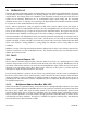
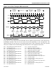
11.1.2 Timer/Counter Control Register (TCON) Summary
7 6 5 4 3 2 1 0
TCON
88h
TF1 TR1
TF0
TR0 IE1 IT1 IE0 IT0
Bit 7: Timer 1 Overflow Flag (TF1). Set to 1 when Timer 1 overflows from FFh and cleared when the
processor vectors to the interrupt service routine.
Bit 6: Timer 1 Run Control (TR1). Turns on Timer 1 when this bit is set.
Bit 5: Timer 0 Overflow Flag (TF0). Set to 1 when Timer 0 overflows from FFh, and cleared when the
processor vectors to the interrupt service routine.
Bit 4: Timer 0 Run Control (TR0). Turns on Timer 0 when this bit is set to 1.
Bit 3: Interrupt 1 Edge Detect (IE1). Set by hardware when an edge/level is detected on INT1 .
Bit 2: Interrupt 1 Type Select (IT1). INT1 detects a falling edge when this bit is set to 1. INT1 detects a
low level when this bit is 0.
Bit 1: Interrupt 0 Edge Detect (IE0). Set by hardware when an edge/level is detected on
INT0
.
Bit 0: Interrupt 0 Type Select (IT0). INT0 detects a falling edge when this bit is set to 1. INT0 detects a
low level when this bit is 0.
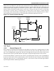
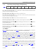
11.2 Mode 0
Mode 0 configures either Timer 0 or Timer 1 for operation as a 13-bit Timer/Counter. As shown in
Figure 11-1
, bits M1 = 0 and M0 = 0 of the TMOD register select this operating mode.
When using Timer 0, TL0 uses only bits 0–4. These bits serve as the 5 LSbs of the 13-bit timer. TH0
provides the 8 MSbs of the 13-bit timer. Bit 4 of TL0 is used as a ripple out to TH0 bit 0, thereby
completely bypassing bits 5 through 7 of TL0. Once the timer is started using the TR0 (TCON
.4) timer
enable, the timer will count as long as GATE (TMOD
.3) is 0 or GATE is 1 and pin INT0 is 1. It will
count oscillator cycles if C/
T (TMOD.2) is set to a logic 0 and 1-to-0 transitions on T0 (P3.4) if C/ T is
set to a 1. When the 13-bit count reaches 1FFFh (all ones), the next count will cause it to roll over to
0000h. The TF0 (TCON
.5) flag will be set and an interrupt will occur if enabled. The upper three bits of
TL0 will be indeterminate.
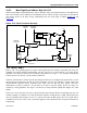
Note that when used as a timer, the time base may be either oscillator cycles/12 or oscillator cycles/4 as
selected by bits TnM (n = 0 or 1) of the CKCON
register. This feature is described in more detail below.
Mode 0 operates identically when Timer 1 is used. The same information applies to TL1
and TH1, which
form the 13-bit register. TR1 (TCON
.6), INT1 (P3.3), T1 (P3.5), and the relevant C/T (TMOD.6) and
GATE (TMOD
.7) bits have the same functions.