
Manual


High-Speed Microcontroller User’s Guide
Rev: 062210 119 of 176
location of their flags. The registers are described below. Following this is a detailed explanation of the
four operating modes.
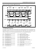
Each timer consists of a 16-bit register in two bytes. These are called TL0
, TH0, TL1, and TH1. As
shown, each timer is broken into low and high bytes. Software
can read or write any of these locations at
any time.
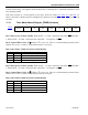
11.1.1 Timer Mode Control Register (TMOD) Summary
7 6 5 4 3 2 1 0
TMOD
89h
GATE
C/
T M1
M0 GATE
C/T
M1 M0
Bit 7: Timer 1 Gate Control (GATE). When GATE = 1, Timer 1 will clock only when INT1 and TR1 =
1. When GATE = 0, Timer 1 will clock only when TR1 = 1 irrespective of
INT1 .
Bit 6: Counter/Timer Select (C/T). When C/T is set to a 0, Timer 1 is incremented by internal clocks.
When C/
T is set to a 1, Timer 1 counts based on the T1 (P3.5) pin.
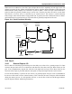
Bits 5 and 4: Timer 1 Mode Select Bit 1 and 0 (M[1:0])
M1 M0 MODE
0 0 Mode 0: 8 bits with 5-bit prescale
0 1 Mode 1: 16 bits
1 0 Mode 2: 8 bits with auto-reload
1 1 Mode 3: Timer 1 stopped
Bit 3: Timer 0 Gate Control (GATE). When GATE = 1, Timer 0 will clock only when
INT0
and TR0 =
1. When GATE = 0, Timer 0 will clock only when TR0 = 1 irrespective of
INT0 .
Bit 2: Counter/Timer Select (C/T). When C/T is set to a 0, Timer 0 is incremented by internal clocks.
When C/
T is set to a 1, Timer 0 counts based on the T0 (P3.4) pin.
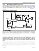
Bits 1 and 0: Timer 0 Mode Select Bit 1 and 0 (M[1:0])
M1 M0 MODE
0 0 Mode 0: 8 bits with 5-bit prescale
0 1 Mode 1: 16 bits
1 0 Mode 2: 8 bits with auto-reload
1 1 Mode 3: Timer 0 is two 8-bit timers