
Manual


High-Speed Microcontroller User’s Guide
Rev: 062210 116 of 176
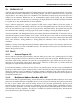
altered by a read operation. Therefore, if a logic 0 is driven onto a port pin from an external source, then
removed, the pin will revert to the weak pullup as determined by the internal latch.
10.7 Read-Modify-Write Instructions
The normal read instructions will read the pin state without regard to the output data latch. The only
exception is the read-modify-write category of instructions. They are listed as follows.
10.8 Instruction Description
ANL Logical AND
ORL Logical OR
XRL Logical Exclusive OR (XOR)
JBC Branch if bit set then clear bit
CPL Complement bit
INC Increment
DEC Decrement
DJNZ Decrement and branch if not zero
MOV PX.n, C Move the carry bit to bit n of port X
CLR PX.n Clear bit n of port X
SETB PX.n Set bit n of port X
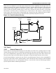
The read-modify-write instructions read the state of the latch, then write back the result to the latch. Thus
the operation takes place using the value that was originally written to the SFR, without regard to the pin
state. The last three instructions listed above are read-modify-write because they read the entire port latch,
then write back the changed value. In this case, only one bit will be changed as specified by the
instruction.
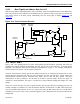
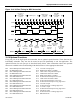
10.9 I/O Port Timing
Figure 10-1 shows when port pins change in relationship to instruction timing. The example shown uses a
MOV command to change P1.0 from a logic 1 to a logic 0. This diagram is presented to aid the designer
in determining the timing relationship for very critical designs. Most designers will not need to consider
this much detail. Dummy NOP instructions are shown to illustrate subsequent instructions.