Application Note: HFAN-9.5.0 Rev.1; 04/08 Pattern Creator/Converter Software User Manual Functional Diagrams Pin Configurations appear at end of data sheet. Functional Diagrams continued at end of data sheet. UCSP is a trademark of Maxim Integrated Products, Inc.
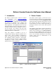
Pattern Creator/Converter Software User Manual 1 Introduction 2 Pattern Creator The Pattern Creator/Converter software (available for download at: http://www.maximic.com/tools/other/) was written to facilitate the creation and use of complicated and non-standard test patterns for evaluation of ICs, modules, and systems used in fiber-optic, video, backplane and other applications.
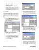
Table 1: PRBS Pattern Length / Tap Positions 2.1 PRBS Patterns The Pseudo Random Bit Sequences (PRBS) are generated using a software version of the conventional hardware shift register with the taps of minimum shift algorithms generated from Galoisfield arithmetic (Figure 2, Table 1, see References 1 & 2). The shift register length is determined by the pattern title. For example, a PRBS 27-1 pattern would be generated using a shift register 7 bits long.
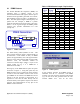
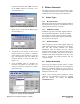
2.2 K28.5 Pattern By pressing the K28.5 button, the user can add one or multiple K28.5 sequences with the choice of being inverted or non-inverted (Figure 4). The data bits added for each K28.5 sequence is the entire K28.5± pattern, where the non-inverted bits are: 1100 0001 0100 1111 1010. Figure 6. Binary File Options This feature can also be used to read in an existing pattern/text file and determine its statistics. This can be a useful tool in evaluating test files or actual data in the system. 2.
• • 2.7 Many pattern generators can only use pattern files up to 8 million bits in length and may have limitations to the number of CIDs that they can tolerate. Once the Done button is pressed the pattern sequence and statistics are erased. The information should be written down before pressing the Done button if it will be needed at a later time.
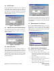
sequence list adds the letters INV to the end of the PRBS sequence to indicate it was inverted (Figure 14). 3 Pattern Converter The pattern Converter section of the software readsin existing patterns and converts them to one of three formats for use with common pattern generators. 3.1 Figure 12. Creator Example Step #6 7. Repeat Step 5 except with the Zeros option selected (Figure 13). 3.1.1 Hex Pattern Files HEX pattern files can be used with Agilent N4901/2 and 86130 pattern generators.
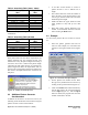
• Table 2: Granularity Table (70841 / 70843) Pattern Length (L) (Bits) Step Size (Bits) • L < 32000 1 2 32000 L < 64000 64000 L < 128000 4 8 128000 L < 256000 256000 L < 512000 16 512000 L < 1024000 32 64 1024000 L < 2048000 2048000 L < 4096000 128 256 4096000 L 8000000* *The Maxim pattern length for the 70841 is 4194304 bits • • 3.
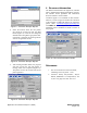
4 Resources/Information The Resources/Information tab (Figure 20) includes links to helpful Maxim Integrated Products websites, the software license agreement and information about the software version number. Figure 17. Converter Example Step #3 4. Select the location where the new pattern file should be stored and click the Save button (Figure 18). Note: Do not change the filename when using DAT-type pattern files. If the name is changed, the pattern generator will not recognize the test file.