
Owner manual


DS4830 User’s Guide
134
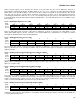
15.5.5 – GPIO Port 6 External Interrupt Flag Register (EIF6)
Bit #
7
6
5
4
3
2
1
0
Name
Reserved
IE6
IE5
IE4
IE3
IE2
IE1
IE0
Reset
0
0
0
0
0
0
0
0
Access
r
rw
rw
rw
rw
rw
rw
rw
These bits are set when a negative edge (IESP6.n = 1) or a positive edge (IESP6.n = 0) is detected on the P6.n pin.
Setting any of the bits to ‘1’ will generate an interrupt to the CPU if the corresponding interrupt is enabled. These bits will
remain set until cleared by software or a reset. These bits must be cleared by software before exiting the interrupt service
routine or another interrupt will be generated as long as the bit remains set.
15.5.6 – GPIO Port 6 External Interrupt Enable Register (EIE6)
Bit #
7
6
5
4
3
2
1
0
Name
Reserved
EX6
EX5
EX4
EX3
EX2
EX1
EX0
Reset
0
0
0
0
0
0
0
0
Access
r
rw
rw
rw
rw
rw
rw
rw
Setting any of these bits to ‘1’ will enable the corresponding external interrupt. Clearing any of the bits to ‘0’ will disable
the corresponding interrupt function.
15.6 – GPIO Code Example
//set pin 6.4 as a high output
PD6 |= 0x10; //set direction PD6.4 to 1 for an output
PO6 |= 0x10; //set the output PO6.4 high
//set pin 6.4 as a high-impedance input
PD6 &= ~0x10; //set direction PD6.4 to 0 for input
PO6 &= ~0x10; //set PO6.4 low to disable weak pullup
//enable the pin 6.4 weak pullup
PD6 &= ~0x10; //set direction PD6.4 to 0 for input
PO6 |= 0x10; //set PO6.4 high to enable weak pullup
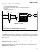
//configure pin6.4 as port ‘Open Drain’
PO6 &= ~0x10; // set the PO6.4 to the logic ‘0’
PD6 |= 0x10; // this will configure P6.4 as output and drive logic ‘0’
PD6 &= ~0x10; // this will configure P6.4 as input with high impedance.
In summary, the GPIO output can be set to the ‘Open Drain’ by doing the following method
1. Set the POp.n to the logic ‘0’.
2. Toggle the direction register PDp.n between the input and output.
This causes the pin to alternate between logic ‘0’ (PDp.n = 1) and ‘high impedance’ (PDp.n = 0).