
Datasheet


DS28EC20: 20Kb 1-Wire EEPROM
17 of 27
speed, the DS28EC20 requires V
PUP
to be 5V ±5%. Note that legacy 1-Wire products support a standard
communication speed of 16.3kbps and overdrive of 142kbps. The slightly reduced rates for the DS28EC20 are a
result of additional recovery times, which in turn were driven by a 1-Wire physical interface enhancement to
improve noise immunity. The value of the pullup resistor primarily depends on the network size and load conditions.
The DS28EC20 requires a pullup resistor of 2.2kΩ (max) at any speed.
The idle state for the 1-Wire bus is high. If for any reason a transaction needs to be suspended, the bus MUST be
left in the idle state if the transaction is to resume. If this does not occur and the bus is left low for more than 16µs
(overdrive speed) or more than 120µs (standard speed), one or more devices on the bus can be reset.
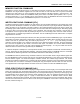
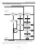
Figure 8. Hardware Configuration
Open-Drain
Port Pin
RX = RECEIVE
TX = TRANSMIT
100Ω
MOSFET
V
PUP
RX
TX
TX
RX
DATA
R
PUP
I
L
BUS MASTER
DS28EC20 1-Wire PORT
TRANSACTION SEQUENCE
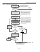
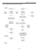
The protocol for accessing the DS28EC20 through the 1-Wire port is as follows:
Initialization
ROM Function Command
Memory Function Command
Transaction/Data
INITIALIZATION
All transactions on the 1-Wire bus begin with an initialization sequence. The initialization sequence consists of a
reset pulse transmitted by the bus master followed by presence pulse(s) transmitted by the slave(s). The presence
pulse lets the bus master know that the DS28EC20 is on the bus and is ready to operate. For more details, see the
1-Wire Signaling section.
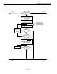
1-Wire ROM FUNCTION COMMANDS
Once the bus master has detected a presence, it can issue one of the seven ROM function commands that the
DS28EC20 supports. All ROM function commands are 8 bits long. See Figure 9 for list of these commands.
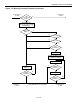
READ ROM [33h]
This command allows the bus master to read the DS28EC20’s 8-bit family code, unique 48-bit serial number, and
8-bit CRC. This command can only be used if there is a single slave on the bus. If more than one slave is present
on the bus, a data collision occurs when all slaves try to transmit at the same time (open drain produces a wired-
AND result). The resultant family code and 48-bit serial number result in a mismatch of the CRC.