
Datasheet


DS28E05 1-Wire EEPROM
www.maximintegrated.com
Maxim Integrated
│
5
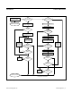
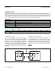
Figure 1. Block Diagram
Figure 2. Hierarchical Structure for 1-Wire Protocol
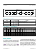
Figure 3. 64-Bit ROM ID
ThepolynomialisX
8
+X
5
+X
4
+1.Additionalinformation
aboutthe1-WireCyclicRedundancyCheckisavailable
in ApplicationNote27:Understanding and Using Cyclic
Redundancy Checks with Maxim iButton® Products.
The shift register bits are initialized to 0. Then, starting
withtheleastsignificantbitofthefamilycode,onebitat
atimeisshiftedin.Afterthe8thbitofthefamilycodehas
beenentered,theserialnumberisentered.Afterthelast
bitoftheserialnumberhasbeenentered,theshiftreg-
istercontainstheCRCvalue.Shiftinginthe8bitsofthe
CRCreturnstheshiftregistertoall0s.
iButton is a registered trademark of Maxim Integrated
Products, Inc.
DS28E05
1-Wire FUNCTION
CONTROL
1-Wire NET
PARASITE POWER
64-BIT
ROM ID
ADMINISTRATIVE DATA
(64 BITS)
USER EEPROM
7 PAGES OF
(128 BITS EACH)
MEMORY
FUNCTION
CONTROL
AVAILABLE COMMANDS: DATA FIELD AFFECTED:
READ ROM
MATCH ROM
SEARCH ROM
SKIP ROM
RESUME
64-BIT ROM ID, RC-FLAG
64-BIT ROM ID, RC-FLAG
64-BIT ROM ID, RC-FLAG
RC-FLAG
RC-FLAG
1-Wire ROM
FUNCTION COMMANDS
WRITE MEMORY
READ MEMORY
USER MEMORY, ADMINISTRATIVE DAT
A
USER MEMORY, ADMINISTRATIVE DAT
A
DS28E05-SPECIFIC
MEMORY FUNCTION COMMANDS
COMMAND LEVEL:
DS28E05
MSb
8-BIT
CRC CODE
48-BIT SERIAL NUMBER
MSb LSb
MSb
LSb
LSb
8-BIT FAMILY CODE
(0Dh)
MSbLSb