
Datasheet


DS28E05 1-Wire EEPROM
www.maximintegrated.com
Maxim Integrated
│
15
The sum of t
RL
+δ(risetime)ononesideandtheinternal
timing generator of the DS28E05 on the other side define
the master sampling window (t
MSR(MIN)
to t
MSR(MAX)
),in
which the master must perform a read from the data line.
For the most reliable communication, t
RL
should be as
shortaspermissible,andthemastershouldreadcloseto
but no later than t
MSR(MAX)
.Afterreadingfromthedata
line, the master must wait until t
SLOT
is expired. This
guarantees sufficient recovery time t
REC
for the DS28E05
togetreadyforthenexttimeslot.Notethatt
REC
specified
herein applies only to a single DS28E05 attached to a
1-Wireline.Formultideviceconfigurations,t
REC
must be
extended to accommodate the additional 1-Wire device
input capacitance.
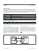
Improved Network Behavior
(Switchpoint Hysteresis)
Ina1-Wireenvironment,lineterminationispossibleonly
during transients controlled by the bus master (1-Wire
driver). 1-Wire networks, therefore, are susceptible to
noise of various origins. Depending on the physical size
and topology of the network, reflections from end points
and branch points can add up or cancel each other to
some extent. Such reflections are visible as glitches or
ringingonthe1-Wirecommunication line.Noisecoupled
onto the 1-Wire line from external sources can also result
insignalglitching.Aglitchduringtherisingedgeofatime
slot can cause a slave device to lose synchronization
with the master and, consequently, result in a Search
ROM command coming to a dead end or cause a device-
specific function command to abort. The DS28E05 uses a
1-Wire front-end with built-in hysteresis at the low-to-high
switchingthresholdV
TH
.IfanegativeglitchcrossesV
TH
butdoesnotgobelowV
TL
,itisnotrecognized(Figure11).
1-Wire Communication Examples
See Table 5 and Table 6 for the 1-Wire communication
legend and data direction codes.
Figure 11. Noise Suppression Scheme
Table 5. 1-Wire Communication Legend
Table 6. Data Direction Codes
SYMBOL DESCRIPTION
RST 1-Wire reset pulse generated by master
PD 1-Wire presence detect pulse generated by slave
Select
CommandanddatatosatisfytheROMfunctionprotocol
PB Parameter byte
CS
CommandSuccessindicator
Release FFhbytesentbythemastertostartawriteactivityintheslave
WM Command“WriteMemory”
RM Command“ReadMemory”
<n bytes> Transfer of n bytes
<data to EOP> Transfer of as many bytes as are needed to reach the end of the page
Data Transfer of 2 bytes segment data
FFloop IndeniteloopwherethebusmasterreadsFFhbytes
Master-to-Slave Slave-to-Master Master waits (1-Wire idle high)
V
PUP
V
TH
V
TL
V
HY
0V