
Datasheet


DS28E05 1-Wire EEPROM
www.maximintegrated.com
Maxim Integrated
│
13
Resume Command [A5h]
To maximize the data throughput in a multidrop environ-
ment,theResumecommandisavailable.Thiscommand
checksthestatus of theRCbit and, if itisset, directly
transfers control to the memory functions, similar to a
SkipROMcommand.TheonlywaytosettheRCbitis
through successfully executing the Match ROM or Search
ROMcommand.OncetheRCbitisset,thedevicecan
repeatedly be accessed through the Resume command.
AccessinganotherdeviceonthebusclearstheRCbit,
preventing two or more devices from simultaneously
responding to the Resume command.
1-Wire Signaling
The DS28E05 requires strict protocols to ensure data
integrity. The protocol consists of four types of signaling
ononeline:resetsequencewithresetpulseandpresence
pulse,write-zero,write-one,andread-data.Exceptforthe
presencepulse,thebusmasterinitiatesallfallingedges.
The DS28E05 communicates at overdrive speed only.
Togetfromidletoactive,thevoltageonthe1-Wireline
needstofallfromV
PUP
belowthethresholdV
TL
. To get
fromactivetoidle,thevoltageneedstorisefromV
IL(MAX)
pastthethresholdV
TH
. The time it takes for the voltage
to make this rise is seen in
Figure9asε,anditsduration
depends on the pullup resistor (R
PUP
) used and the
capacitance of the 1-Wire network attached. The voltage
V
IL(MAX)
is relevant for the DS28E05 when determining a
logicallevel,nottriggeringanyevents.
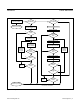
Figure 9 shows the initialization sequence required to
begin any communication with the DS28E05. A reset
pulse followed by a presence pulse indicates that the
DS28E05isreadytoreceivedata,giventhecorrectROM
and memory function command. If the bus master uses
slew-ratecontrolonthefallingedge,itmustpulldownthe
line for t
RSTL
+t
F
to compensate for the edge.
After the bus master has released the line it goes into
receivemode.Nowthe1-WirebusispulledtoV
PUP
through
thepullupresistor.WhenthethresholdV
TH
iscrossed,the
DS28E05 waits and then transmits a presence pulse by
pullingthelinelow.Todetectapresencepulse,themaster
must test the logical state of the 1-Wire line at t
MSP
.
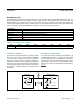
Read-/Write-Time Slots
Data communication with the DS28E05 takes place in
time slots that carry a single bit each. Write time slots
transport data from bus master to slave. Read time slots
transfer data from slave to master.
Figure 10 illustrates
the definitions of the write- and read-time slots.
Allcommunicationbeginswiththemasterpullingthedata
line low. As the voltage on the 1-Wire line falls below
thethresholdV
TL
,theDS28E05startsitsinternaltiming
generator that determines when the data line is sampled
during a write time slot and how long data is valid during
a read time slot.
Master-to-Slave
For a write-one time slot, the voltage on the data line
must have crossed the V
TH
threshold before the write-
one low time t
W1L(MAX)
isexpired.Forawrite-zerotime
slot, the voltage on the data line must stay below the
V
TH
threshold until the write-zero low time t
W0L(MIN)
is
expired.Forthemostreliablecommunication,thevoltage
onthedatalineshouldnotexceedV
IL(MAX)
during the
entire t
W0L
or t
W1L
window.AftertheV
TH
threshold has
beencrossed,theDS28E05needsarecoverytimet
REC
before it is ready for the next time slot.
Figure 9. Initialization Procedure: Reset and Presence Pulse
RESISTOR MASTER DS28E05
t
RSTL
t
RSTH
MASTER Tx "RESET PULSE" MASTER Rx "PRESENCE PULSE"
V
PUP
V
IHMASTER
V
TH
V
TL
V
IL(MAX)
0V
ε
t
F
t
REC
t
MSP